Parts
No parts specified.
-
-
Before disassembling the Samsung Galaxy Note 2, thoroughly wash and dry your hands.
-
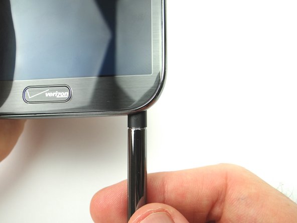
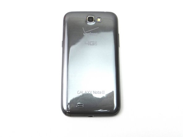
Remove the battery cover, battery and stylus pen. Place into ZONE I.
-
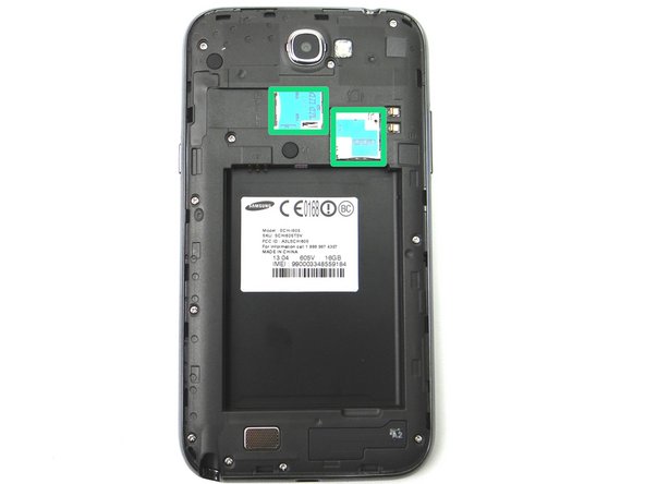
Remove SIM card, and SD card. Place in COMPARTMENT A.
-
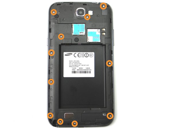
Remove eleven 4.0 mm Phillips screws. Place into SLOT 1.
-
-
-
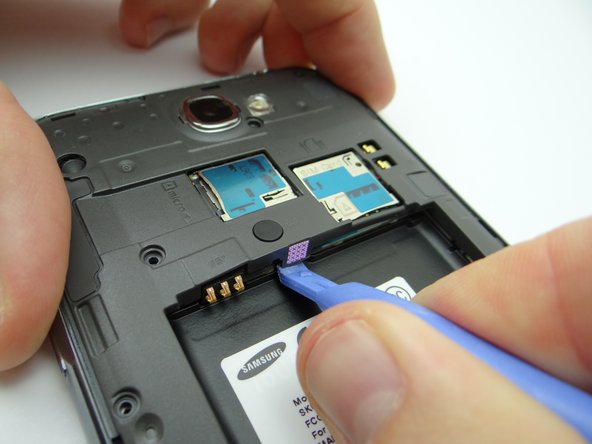
Make sure the tip of the Blue Pry Tool is facing the bottom of the phone before inserting it between mid-frame and front panel, as in Picture 1. (picture of blue pry tool facing bottom of the phone right next to insertion point).
-
Picture 1: Starting in the bottom right corner, use the Blue Pry Tool to separate the mid-frame from the front panel. Work your way around the phone until you free the mid-frame from the font panel.
-
-
-
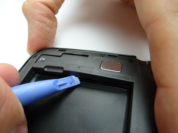
Pictures 1 & 2: Use the Blue Pry Tool to free the clips on the bottom and top of the battery holding area.
-
-
-
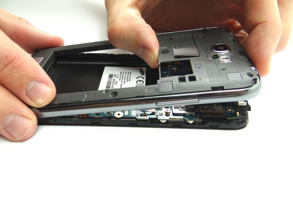
Once all clips connecting the mid-frame to the front assembly are freed, use your fingers to gently lift the mid-frame away from the phone.
-
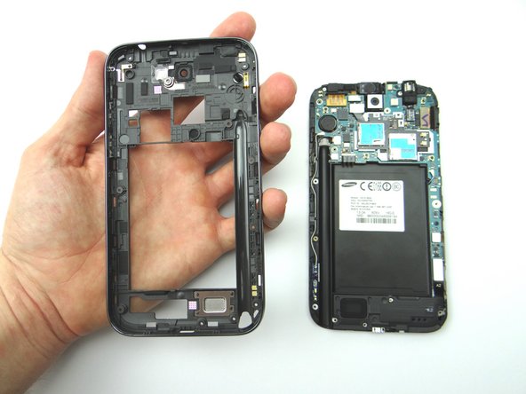
Place mid-frame into ZONE II.
-
-
-
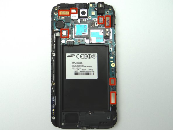
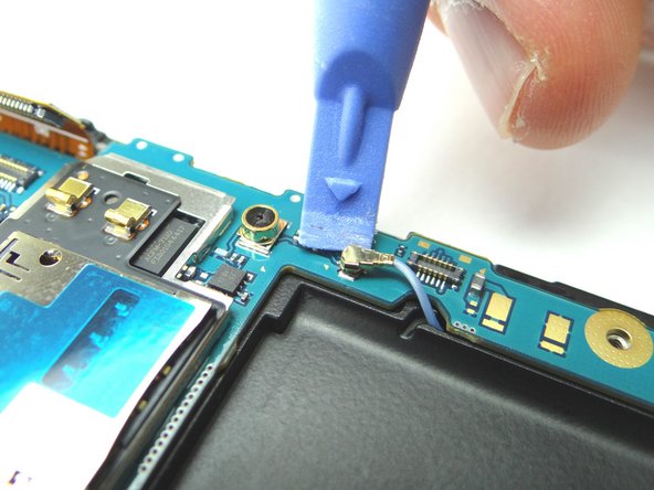
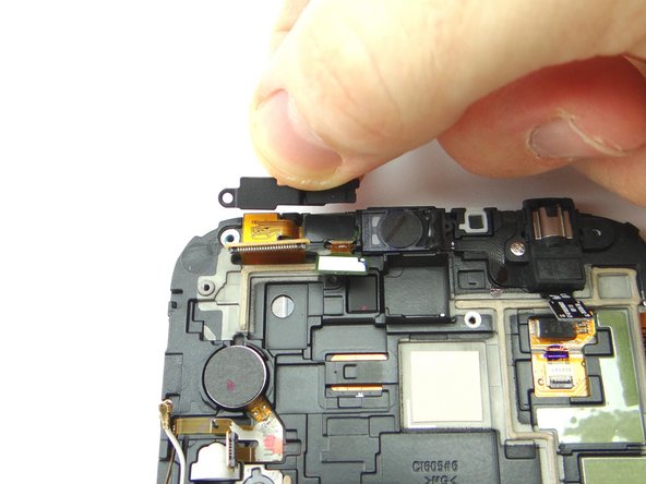
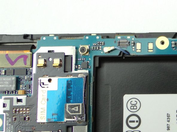
Use the Blue Pry Tool to disconnect the seven ribbon cable connectors on the logic board.
-
-
-
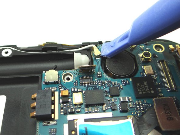
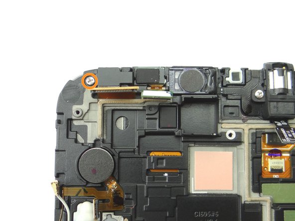
Disconnect the WiFi antenna connector.
-
Disconnect the cellular antenna connector.
-
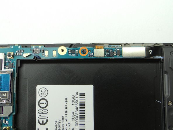
Remove one 2.9 mm Phillips screw and place into SLOT 2.
-
-
-
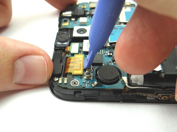
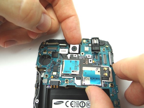
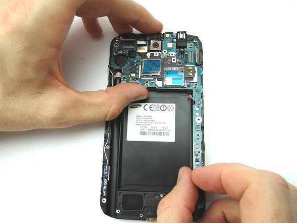
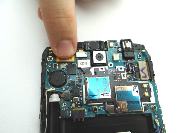
Use your index finger to gently ease the camera out of its position while lifting the logic board.
-
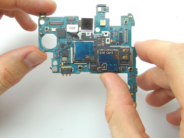
Use your fingers to brush away any ribbon cables while you remove the logic board. Place into ZONE III.
-
-
-
Remove one 2.9 mm Phillips screw and place into SLOT 3.
-
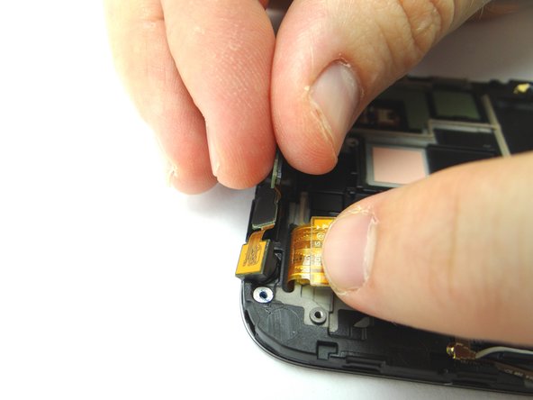
Use the fingers to remove the metal plate covering the front-facing camera/sensor assembly. Place into SLOT 3.
-
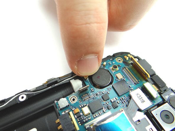
Use your fingers to remove the front-facing camera/sensor assembly and place into COMPARTMENT B.
-
-
-
Replace the front-facing camera/sensor assembly from COMPARTMENT B.
-
Use the fingers to replace the metal plate on top of the front-facing camera/sensor assembly from SLOT 3.
-
Replace one 2.0 mm Phillips screw from SLOT 3.
-
-
-
Replace the logic board from ZONE III. Ensure none of the ribbon cable connectors get stuck under the logic board.
-
Reconnect the WiFi antenna connector.
-
Reconnect the cellular antenna connector.
-
-
-
Replace one 2.9 mm Phillips screw from SLOT 2.
-
Reconnect the seven ribbon cable connectors to the logic board.
-
-
-
Replace mid-frame from ZONE II.
-
Replace eleven 4.0 mm Phillips screws from SLOT 1.
-
Replace the SIM card and SD card from COMPARTMENT A.
-
-
-
Replace the battery cover, battery and stylus pen from ZONE I.
-