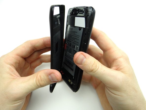
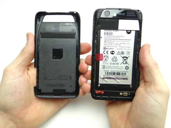
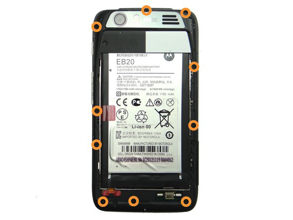
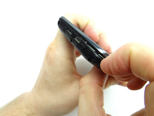
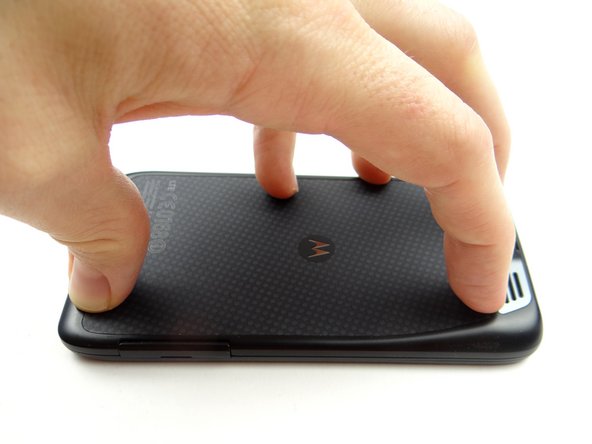
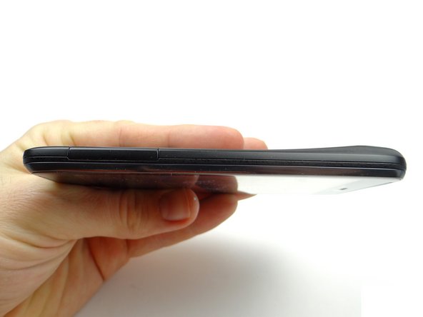
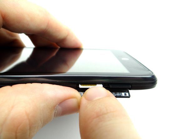
1. Power down the device. Open the SIM tray slot.  Push the SIM card in and it will pop out.  Repeat with the SD card, if present.  Place both in COMPARTMENT A.
    • Power down the device.

    • Open the SIM tray slot. Push the SIM card in and it will pop out. Repeat with the SD card, if present. Place both in COMPARTMENT A.

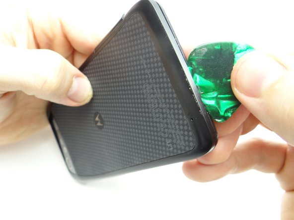
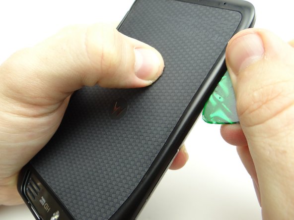
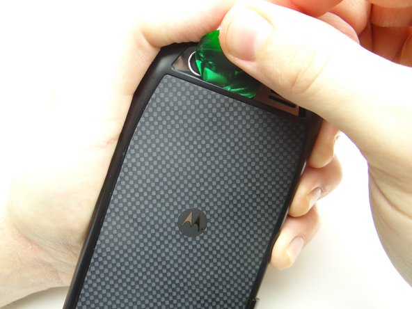
  2. Insert guitar pick in the upper-right corner between the battery cover and display assembly. Work your way down the right side to release clips holding the battery cover in place. Work your way down the right side to release clips holding the battery cover in place.
    • Insert guitar pick in the upper-right corner between the battery cover and display assembly.

    • Work your way down the right side to release clips holding the battery cover in place.

  3. Work your way across the bottom, then up the opposite side to continue releasing clips. Work your way across the bottom, then up the opposite side to continue releasing clips.
    • Work your way across the bottom, then up the opposite side to continue releasing clips.

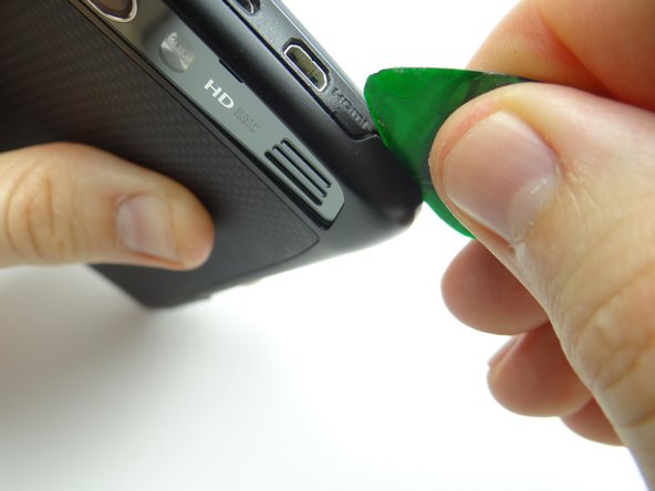
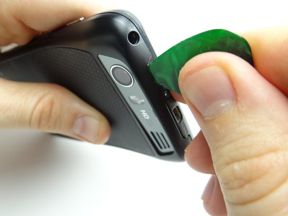
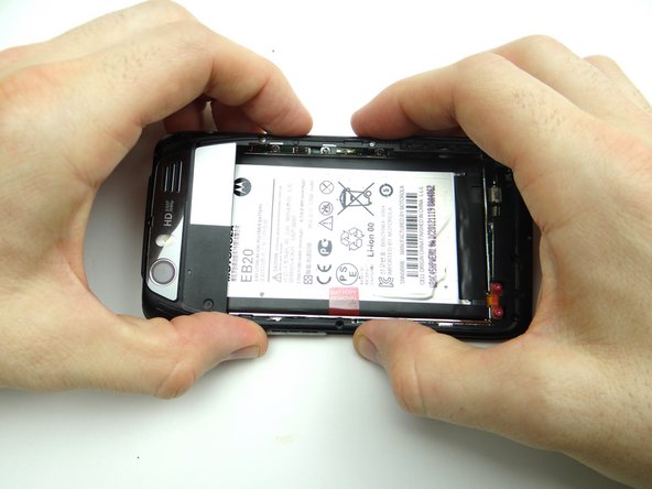
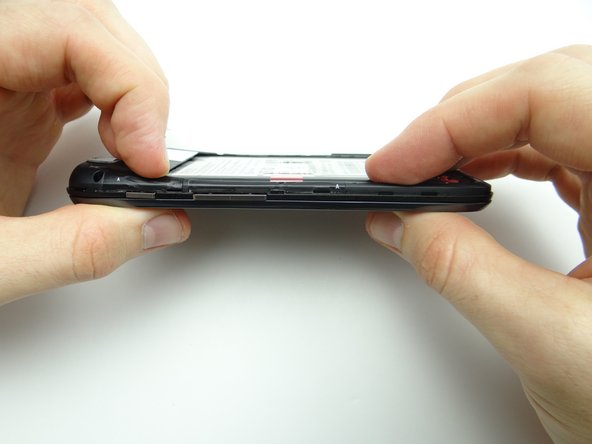
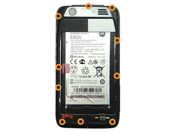
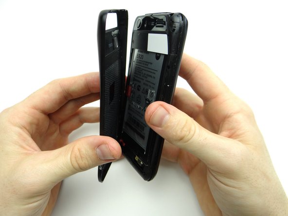
  4. Be careful while performing this step: Picture 1: Release the battery cover clips near the HDMI port. Picture 2: Release clips behind the charging and HDMI ports.
    • Be careful while performing this step:

    • Picture 1: Release the battery cover clips near the HDMI port.

    • Picture 2: Release clips behind the charging and HDMI ports.

    • Picture 3: Release clips below rear camera trim.

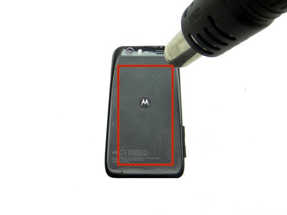
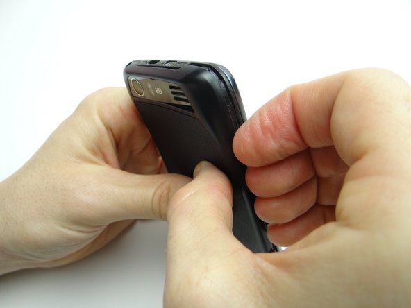
  5. Adhesive holds the battery cover in place. Don't try to remove the battery cover just yet: Picture 1: Heat the battery cover with low-level (100° Celsius heat) for 30 seconds. Picture 2: Use your fingers to peel away the battery cover slightly.
    • Adhesive holds the battery cover in place. Don't try to remove the battery cover just yet:

    • Picture 1: Heat the battery cover with low-level (100° Celsius heat) for 30 seconds.

    • Picture 2: Use your fingers to peel away the battery cover slightly.

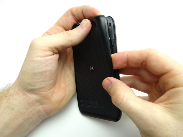
    • Picture 3: Push your finger under the Motorola symbol.

    • The Motorola symbol will stay adhered to the battery as you remove the battery cover if you're not careful!

  6. Continue peeling off battery cover, releasing the clips holding it in place. Place battery cover in ZONE I.
    • Continue peeling off battery cover, releasing the clips holding it in place.

    • Place battery cover in ZONE I.

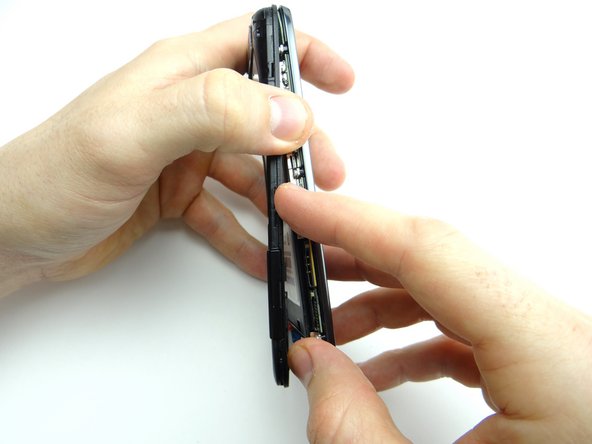
  7. Picture 1: Remove ten 4.8mm T5 Torx screws.  Place in SLOT 1. Picture 2:  Begin separating the mid-frame from the front panel in the upper-left hand corner (opposite the headphone jack). Picture 3: Continue working down the side, opposite the buttons.
    • Picture 1: Remove ten 4.8mm T5 Torx screws. Place in SLOT 1.

    • Picture 2: Begin separating the mid-frame from the front panel in the upper-left hand corner (opposite the headphone jack).

    • Picture 3: Continue working down the side, opposite the buttons.

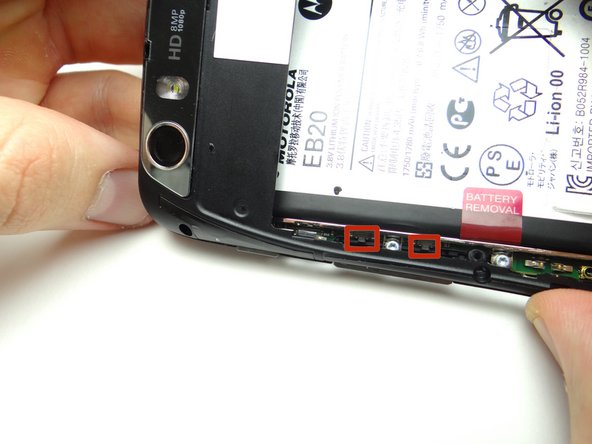
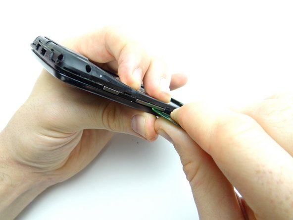
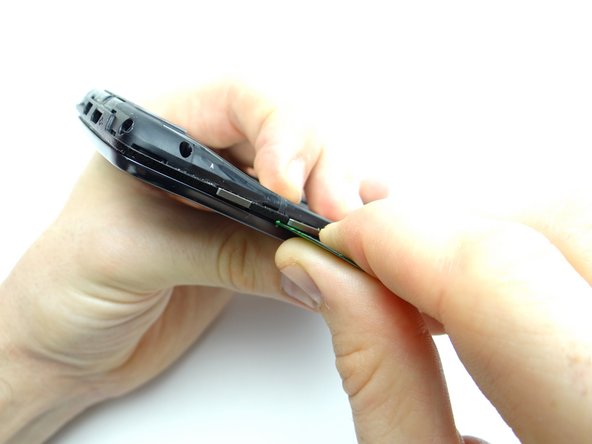
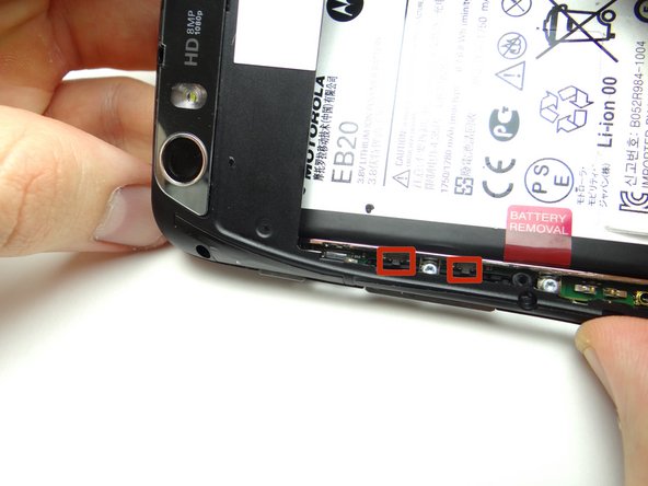
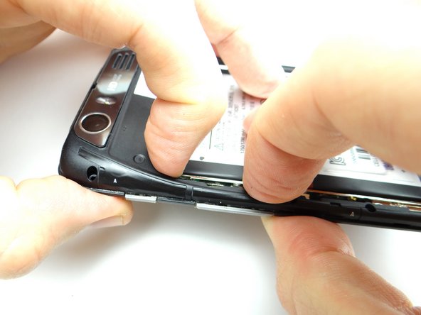
  8. Picture 1: Be careful not to damage the volume rocker clips (red squares) while performing this step: Pictures 2 & 3: Separate the mid-frame under the volume rocker with a guitar pick. Pictures 2 & 3: Separate the mid-frame under the volume rocker with a guitar pick.
    • Picture 1: Be careful not to damage the volume rocker clips (red squares) while performing this step:

    • Pictures 2 & 3: Separate the mid-frame under the volume rocker with a guitar pick.

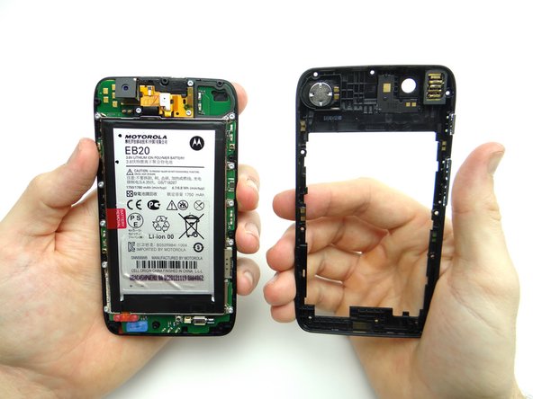
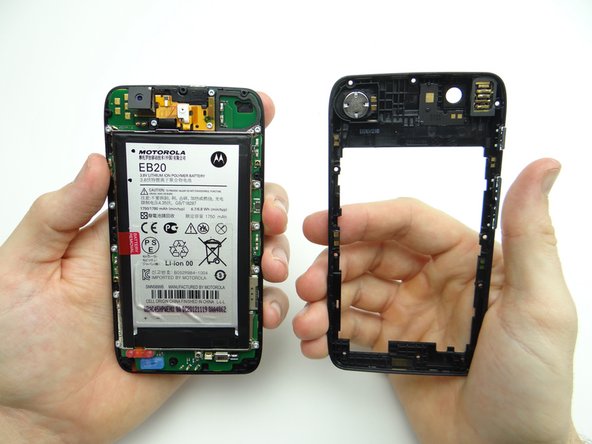
  9. Finish peeling up the mid-frame.
    • Finish peeling up the mid-frame.

    • Place either the mid-frame or front panel in Sandbox ZONE II, depending on the repair needed.

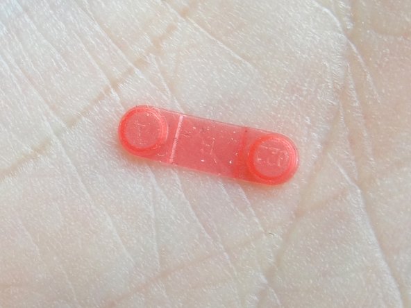
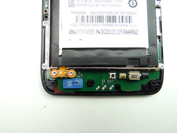
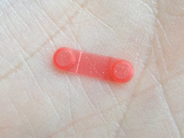
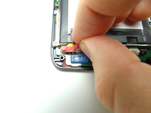
  10. Pictures 1 & 2: Remove the pink rubber screw cover and place in SLOT 2. Picture 3: Remove two 3.3mm T5 Torx screws.  Place in SLOT 2 (with cover). Picture 3: Remove two 3.3mm T5 Torx screws.  Place in SLOT 2 (with cover).
    • Pictures 1 & 2: Remove the pink rubber screw cover and place in SLOT 2.

    • Picture 3: Remove two 3.3mm T5 Torx screws. Place in SLOT 2 (with cover).

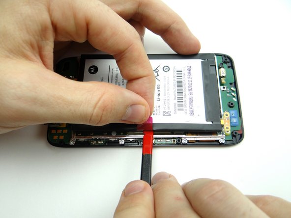
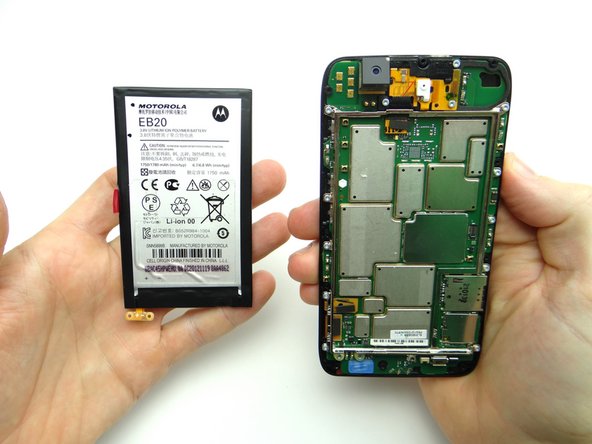
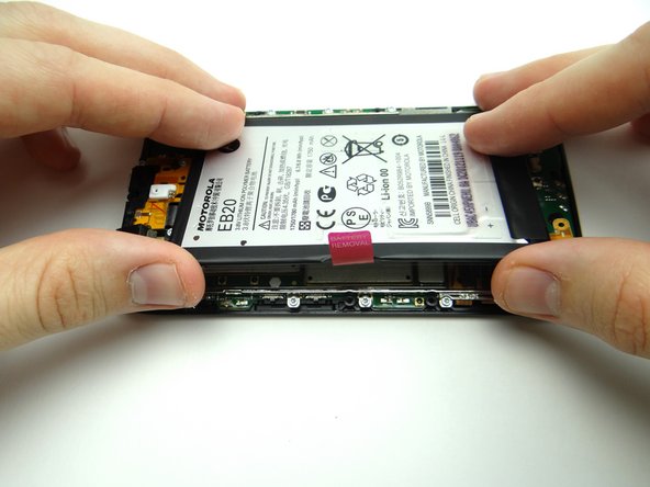
  11. The battery is held down with mild adhesive: Picture 1: Pull on battery tab to create just enough space to wedge flat end of spudger below battery. Picture 2: Work your way to the bottom to release the adhesive.
    • The battery is held down with mild adhesive:

    • Picture 1: Pull on battery tab to create just enough space to wedge flat end of spudger below battery.

    • Picture 2: Work your way to the bottom to release the adhesive.

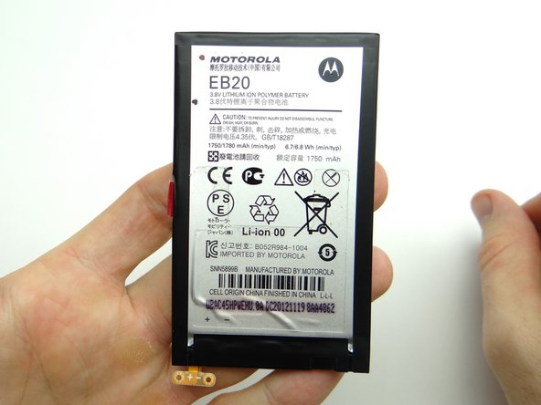
    • Picture 3: Work the battery up, opening it like a book from the left edge.

  12. Place the battery on top of the battery cover in ZONE I.
    • Place the battery on top of the battery cover in ZONE I.

  13. Replace battery from ZONE I. Replace battery from ZONE I.
    • Replace battery from ZONE I.

  14. Picture 1: Replace two 3.3mm T5 Torx screws from SLOT 2. Pictures 2 & 3: Replace the pink rubber screw cover, also in SLOT 2. Pictures 2 & 3: Replace the pink rubber screw cover, also in SLOT 2.
    • Picture 1: Replace two 3.3mm T5 Torx screws from SLOT 2.

    • Pictures 2 & 3: Replace the pink rubber screw cover, also in SLOT 2.

  15. Picture 1: Seat mid-frame on phone: Pictures 2 & 3: Pivot the volume rocker on the mid-frame around the volume rocker tabs on the logic board, then snap this area of the mid-frame into place first. Pictures 2 & 3: Pivot the volume rocker on the mid-frame around the volume rocker tabs on the logic board, then snap this area of the mid-frame into place first.
    • Picture 1: Seat mid-frame on phone:

    • Pictures 2 & 3: Pivot the volume rocker on the mid-frame around the volume rocker tabs on the logic board, then snap this area of the mid-frame into place first.

  16. Picture 1: Continue snapping mid-frame into place. Picture 2: Check the perimeter to ensure the mid-frame is completely seated. Picture 3: Replace ten 4.8mm black T5 Torx screws from SLOT 1.
    • Picture 1: Continue snapping mid-frame into place.

    • Picture 2: Check the perimeter to ensure the mid-frame is completely seated.

    • Picture 3: Replace ten 4.8mm black T5 Torx screws from SLOT 1.

  17. Picture 1: From ZONE I seat battery cover, buttons side first. Picture 2: Push battery cover into place. Picture 3: Check around the perimeter to ensure all edges are snapped into place.
    • Picture 1: From ZONE I seat battery cover, buttons side first.

    • Picture 2: Push battery cover into place.

    • Picture 3: Check around the perimeter to ensure all edges are snapped into place.

  18. Replace SIM card and SD card from COMPARTMENT A. Power up and test device.
    • Replace SIM card and SD card from COMPARTMENT A.

    • Power up and test device.

Finish Line

James Linder

Member since: 01/24/2013

71,591 Reputation

217 Guides authored

0 Comments

Add Comment

View Statistics:

Past 24 Hours: 1

Past 7 Days: 1

Past 30 Days: 1

All Time: 25

CELL PHONE SANDBOX