Parts

No parts specified.

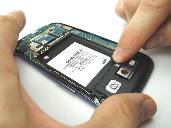
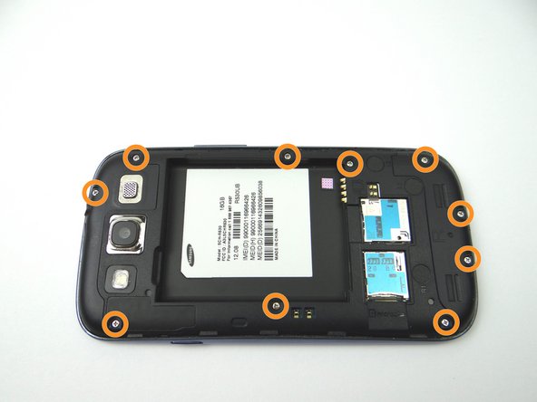
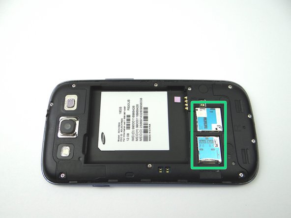
  1. Before disassembling the Samsung Galaxy S3, thoroughly wash and dry your hands. Picture 1: Remove battery cover and battery. Place into ZONE I. Picture 2: Remove SIM card, and SD card.  Place in COMPARTMENT A.
    • Before disassembling the Samsung Galaxy S3, thoroughly wash and dry your hands.

    • Picture 1: Remove battery cover and battery. Place into ZONE I.

    • Picture 2: Remove SIM card, and SD card. Place in COMPARTMENT A.

    • Picture 3: Remove ten 4.0 mm Phillips screws. Place in SLOT 1.

  2. Use your fingers to pull the mid-frame away from the phone. Place into ZONE II. Use your fingers to pull the mid-frame away from the phone. Place into ZONE II.
    • Use your fingers to pull the mid-frame away from the phone. Place into ZONE II.

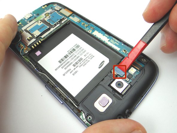
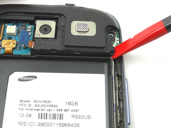
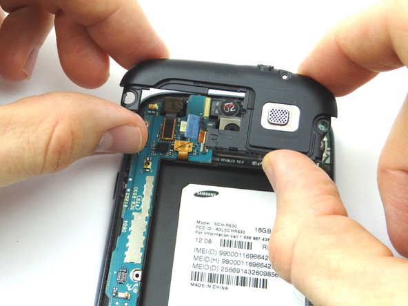
  3. Picture 1: Use the Black Spudger to release the headphone jack/speaker assembly cable. Picture 2: Place the flat tip of the Black Spudger in the bottom right corner of the headphone jack/speaker assembly and gently pry up to release it from the phone. Picture 3: Place headphone jack/speaker assembly into ZONE III.
    • Picture 1: Use the Black Spudger to release the headphone jack/speaker assembly cable.

    • Picture 2: Place the flat tip of the Black Spudger in the bottom right corner of the headphone jack/speaker assembly and gently pry up to release it from the phone.

    • Picture 3: Place headphone jack/speaker assembly into ZONE III.

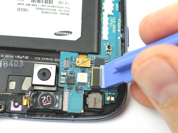
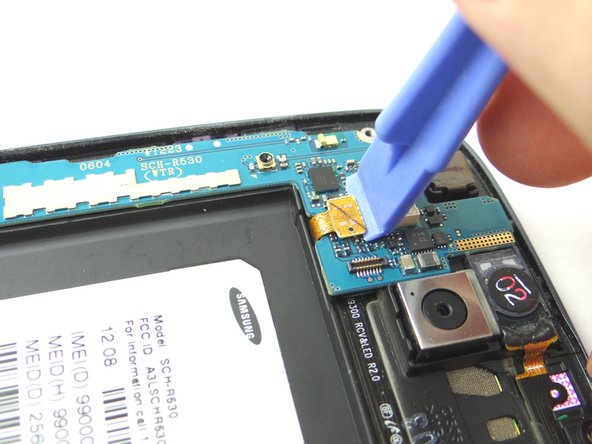
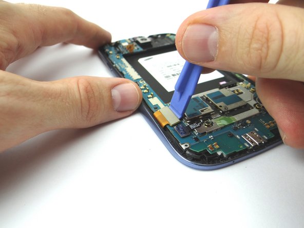
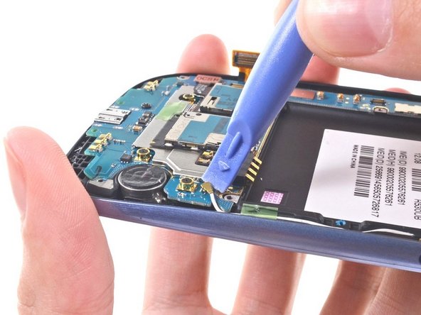
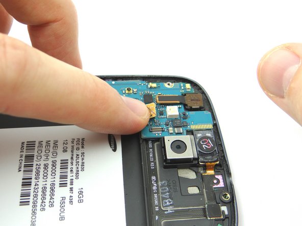
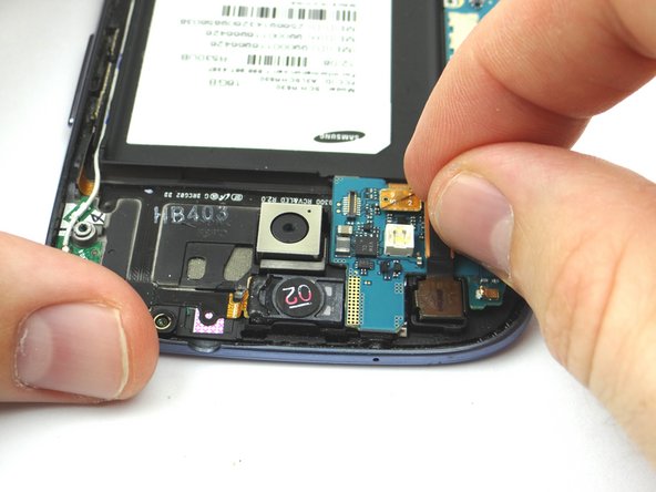
  4. Picture 1: Use the Blue Pry Tool to release the front-facing camera cable. Picture 2: Use the Blue Pry Tool to release the earpiece speaker/volume button cable connector. Picture 3: Use the Blue Pry Tool to release the display assembly cable connecter.
    • Picture 1: Use the Blue Pry Tool to release the front-facing camera cable.

    • Picture 2: Use the Blue Pry Tool to release the earpiece speaker/volume button cable connector.

    • Picture 3: Use the Blue Pry Tool to release the display assembly cable connecter.

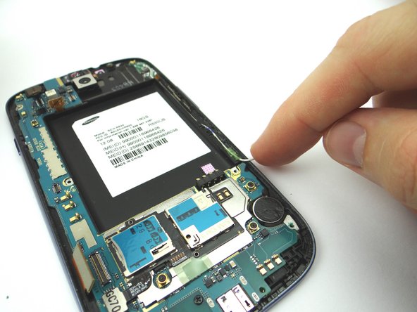
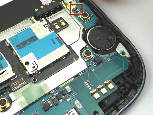
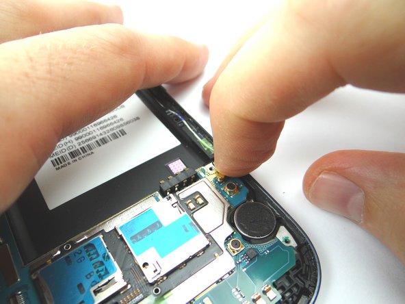
  5. Picture 1: Use the Blue Pry Tool and disconnect the wifi antenna connector. Picture 2: Move the cable to the side with your finger.
    • Picture 1: Use the Blue Pry Tool and disconnect the wifi antenna connector.

    • Picture 2: Move the cable to the side with your finger.

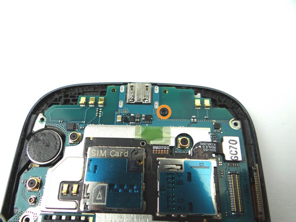
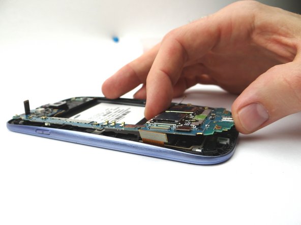
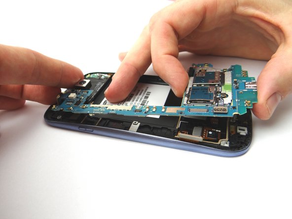
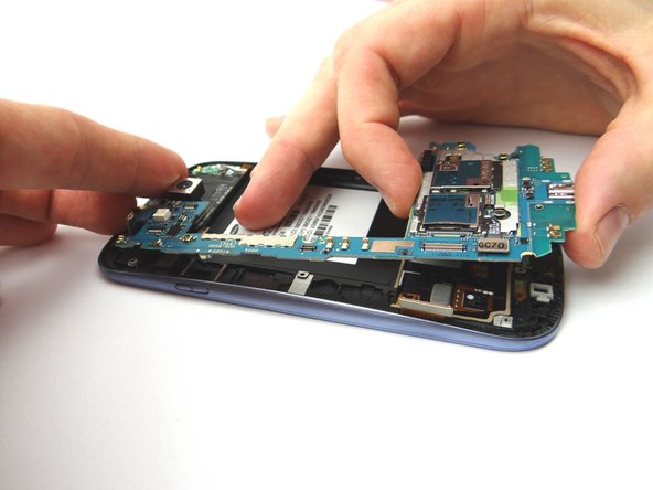
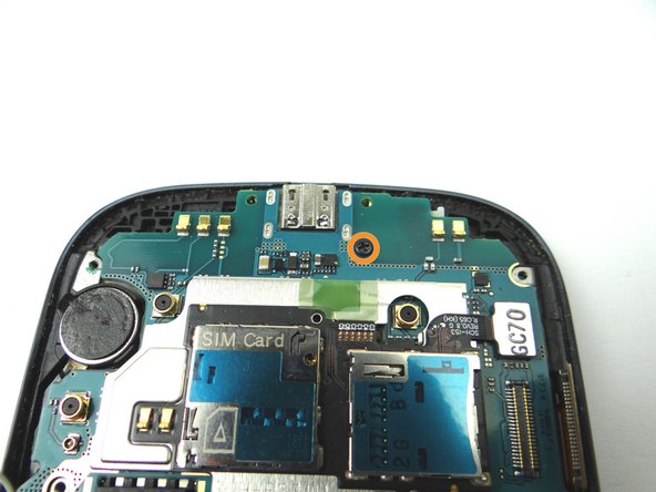
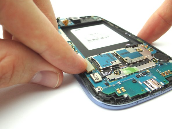
  6. Picture 1: Remove one 3.0 mm and place into SLOT 2. Picture 2 & 3: Lift logic board out of the phone and place into ZONE IV. Brush away cable connectors from the logic board, as you remove it, to avoid ripping them.
    • Picture 1: Remove one 3.0 mm and place into SLOT 2.

    • Picture 2 & 3: Lift logic board out of the phone and place into ZONE IV.

    • Brush away cable connectors from the logic board, as you remove it, to avoid ripping them.

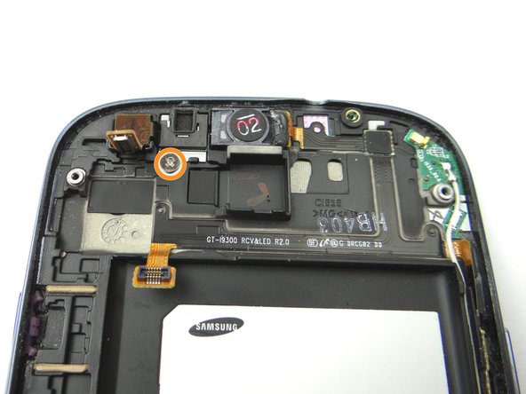
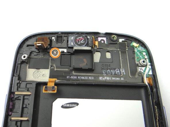
  7. Picture 1: Remove one 2.0 mm Phillips screw and place into SLOT 3. Picture 2: Remove the top microphone casing bracket and place into SLOT 3.
    • Picture 1: Remove one 2.0 mm Phillips screw and place into SLOT 3.

    • Picture 2: Remove the top microphone casing bracket and place into SLOT 3.

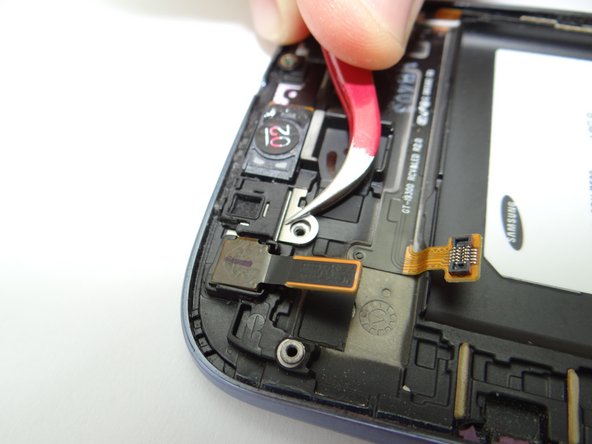
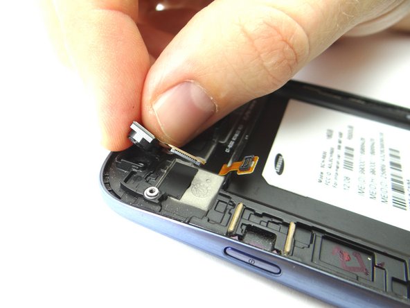
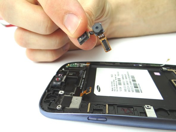
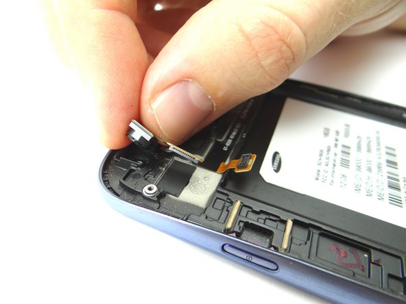
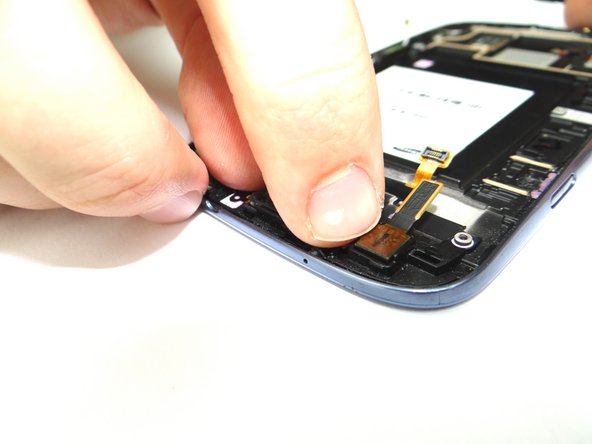
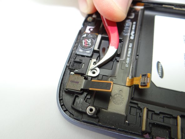
  8. Use your fingers to grasp the front-facing camera and lift from left to right to peel up the ribbon cable that is attached. Place it in COMPARTMENT B. Use your fingers to grasp the front-facing camera and lift from left to right to peel up the ribbon cable that is attached. Place it in COMPARTMENT B.
    • Use your fingers to grasp the front-facing camera and lift from left to right to peel up the ribbon cable that is attached. Place it in COMPARTMENT B.

  9. Picture 1 & 2: Replace the front-facing camera from COMPARTMENT B. Picture 3: Replace the top microphone casing bracket from SLOT 3. Picture 3: Replace the top microphone casing bracket from SLOT 3.
    • Picture 1 & 2: Replace the front-facing camera from COMPARTMENT B.

    • Picture 3: Replace the top microphone casing bracket from SLOT 3.

  10. Replace one 2.0 mm Phillips screw from SLOT 3.
    • Replace one 2.0 mm Phillips screw from SLOT 3.

  11. Picture 1 & 2: Place the logic board onto the phone from ZONE IV. Picture 3: Replace one 3.0 mm screw from SLOT 2. Picture 3: Replace one 3.0 mm screw from SLOT 2.
    • Picture 1 & 2: Place the logic board onto the phone from ZONE IV.

    • Picture 3: Replace one 3.0 mm screw from SLOT 2.

  12. Picture 1: Reattach display assembly cable connector. Picture 2: Reattach earpiece speaker/volume button cable connector. Picture 3: Reattach front-facing camera cable connector.
    • Picture 1: Reattach display assembly cable connector.

    • Picture 2: Reattach earpiece speaker/volume button cable connector.

    • Picture 3: Reattach front-facing camera cable connector.

  13. Use your index finger to reattach the wifi antenna cable. Use your index finger to reattach the wifi antenna cable.
    • Use your index finger to reattach the wifi antenna cable.

  14. Picture 1: Replace headphone jack/speaker assembly from ZONE III. Picture 2: Use your finger to reattach the headphone jack/speaker assembly cable.
    • Picture 1: Replace headphone jack/speaker assembly from ZONE III.

    • Picture 2: Use your finger to reattach the headphone jack/speaker assembly cable.

  15. Picture 1 & 2: Replace the mid-frame on the phone from ZONE II. Picture 2: Replace ten 4.0 mm Phillips screws from SLOT 1. Picture 2: Replace ten 4.0 mm Phillips screws from SLOT 1.
    • Picture 1 & 2: Replace the mid-frame on the phone from ZONE II.

    • Picture 2: Replace ten 4.0 mm Phillips screws from SLOT 1.

  16. Replace SIM card and SD card from COMPARTMENT A.
    • Replace SIM card and SD card from COMPARTMENT A.

    • Replace battery cover and battery from ZONE I.

Finish Line

James Linder

Member since: 01/24/2013

71,591 Reputation

217 Guides authored

0 Comments

Add Comment

View Statistics:

Past 24 Hours: 0

Past 7 Days: 0

Past 30 Days: 1

All Time: 37

CELL PHONE SANDBOX