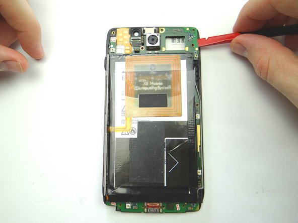
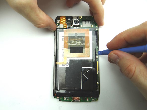
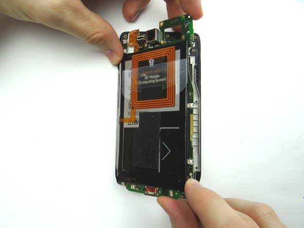
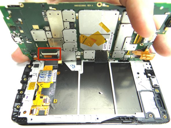
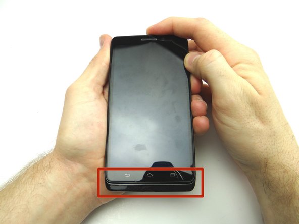
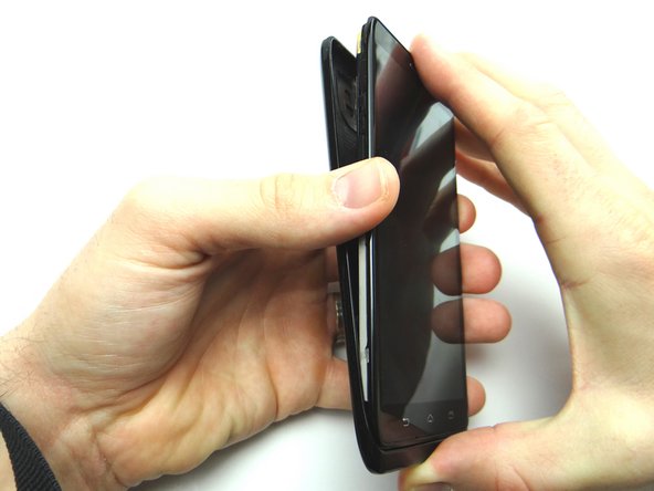
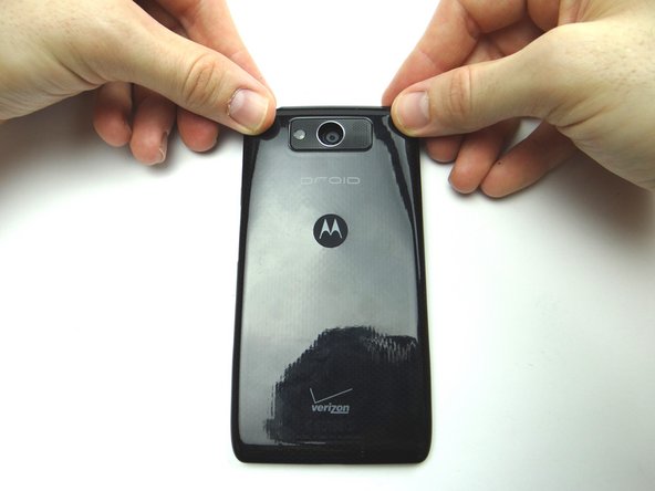
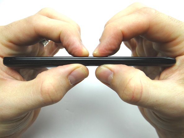
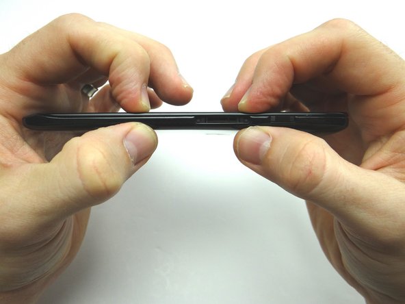
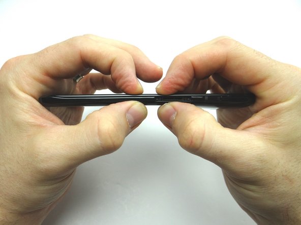
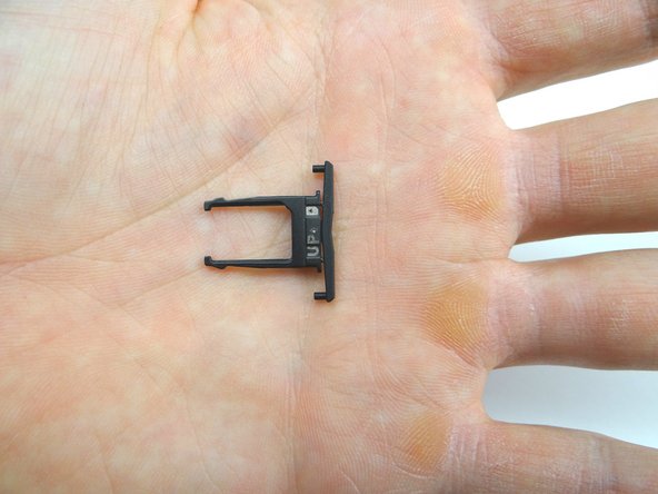
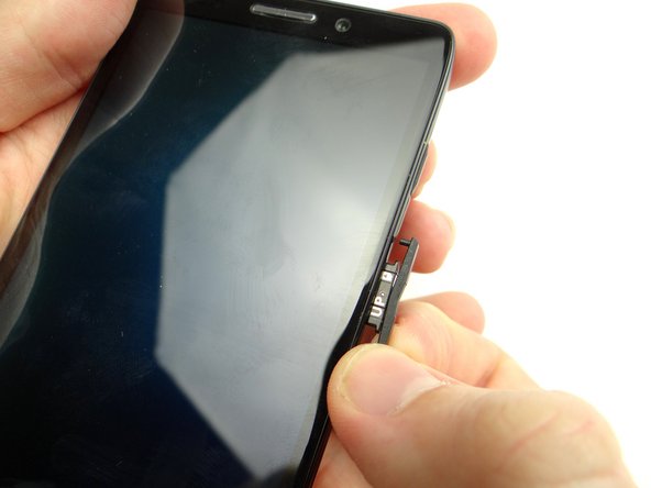
1. Before disassembly, thoroughly wash and dry your hands.  Power down device. The volume rocker doubles as a SIM card tray: pull it out with your fingers.  Place SIM card tray and SIM card (if present) in COMPARTMENT A. The volume rocker doubles as a SIM card tray: pull it out with your fingers.  Place SIM card tray and SIM card (if present) in COMPARTMENT A.
    • Before disassembly, thoroughly wash and dry your hands. Power down device.

    • The volume rocker doubles as a SIM card tray: pull it out with your fingers. Place SIM card tray and SIM card (if present) in COMPARTMENT A.

  2. Insert the blue pry tool between the front panel and battery cover just below the opening for the SIM card tray.  Slowly slide the blue pry tool down the side.
    • Insert the blue pry tool between the front panel and battery cover just below the opening for the SIM card tray. Slowly slide the blue pry tool down the side.

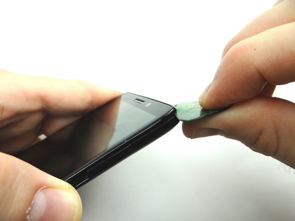
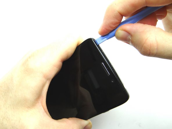
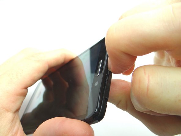
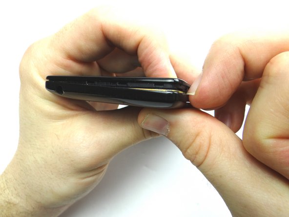
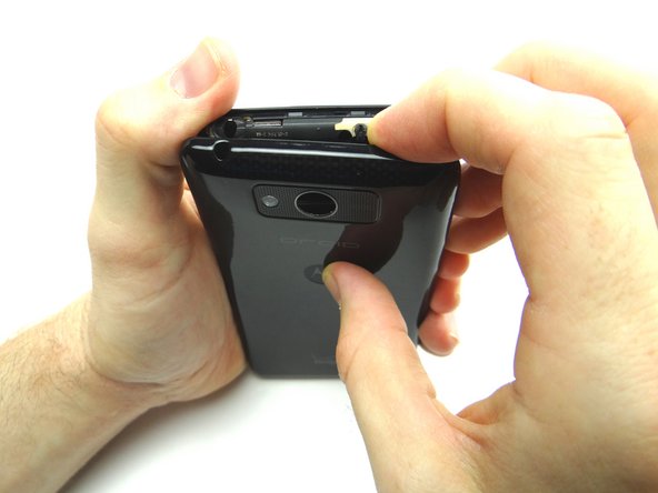
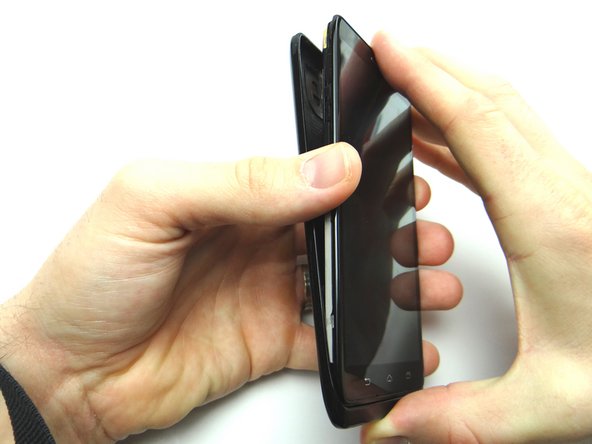
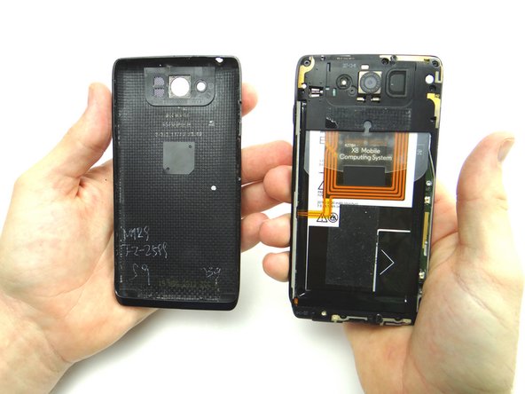
  3. Picture 1: Insert guitar pick between the front panel and battery cover in the upper-right corner.  Sweep down from the corner to SIM card tray opening. Picture 2: Insert blue pry tool in the upper-left corner, then work your way across the top edge. Picture 3: Snag the top of the battery cover with your fingernail and pull it slightly away from the front panel.
    • Picture 1: Insert guitar pick between the front panel and battery cover in the upper-right corner. Sweep down from the corner to SIM card tray opening.

    • Picture 2: Insert blue pry tool in the upper-left corner, then work your way across the top edge.

    • Picture 3: Snag the top of the battery cover with your fingernail and pull it slightly away from the front panel.

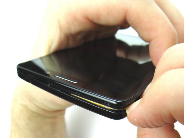
  4. Continue peeling off the corner and nearby edges of the battery cover. Do not try to remove the battery cover just yet!  The battery cover is held in place with adhesive. Do not try to remove the battery cover just yet!  The battery cover is held in place with adhesive.
    • Continue peeling off the corner and nearby edges of the battery cover.

    • Do not try to remove the battery cover just yet! The battery cover is held in place with adhesive.

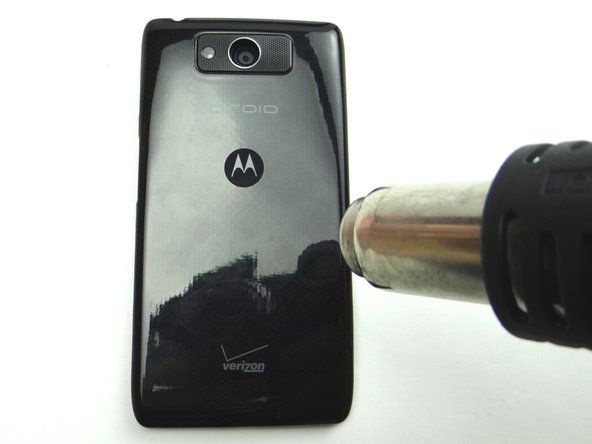
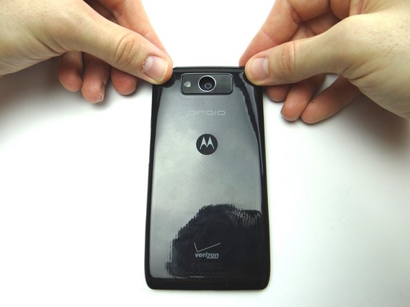
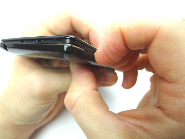
  5. Picture 1: Apply 100° Celsius heat to the center of the back of the phone for 30 seconds to loosen adhesive holding the battery cover in place. Pictures 2 & 3: Peel up the battery cover as much as you can without creating stretch marks. Pictures 2 & 3: Peel up the battery cover as much as you can without creating stretch marks.
    • Picture 1: Apply 100° Celsius heat to the center of the back of the phone for 30 seconds to loosen adhesive holding the battery cover in place.

    • Pictures 2 & 3: Peel up the battery cover as much as you can without creating stretch marks.

  6. Continue working your way around the phone peeling off the battery cover.  Apply heat in 30 second increments if the battery cover won't budge. Place battery cover in ZONE I. Place battery cover in ZONE I.
    • Continue working your way around the phone peeling off the battery cover. Apply heat in 30 second increments if the battery cover won't budge.

    • Place battery cover in ZONE I.

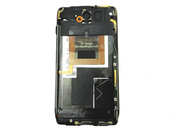
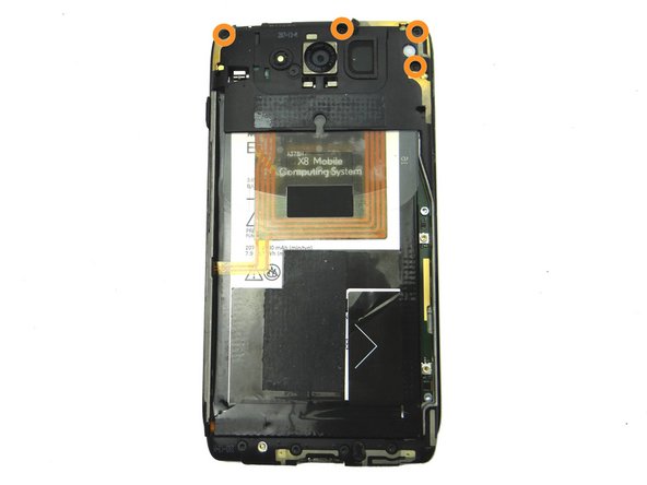
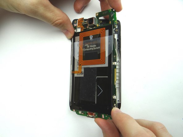
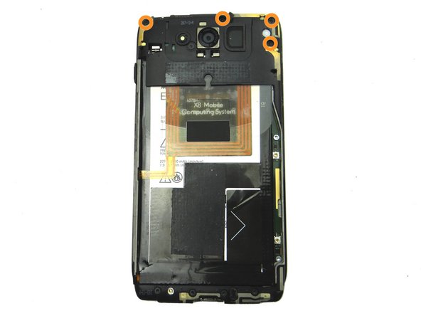
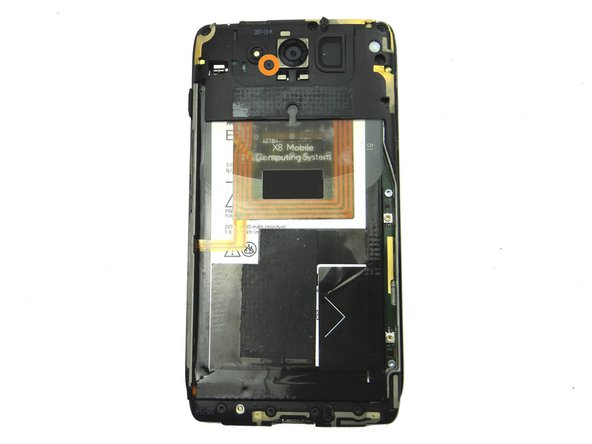
  7. Picture 1: Remove 6.3 mm T3 Torx screw near the lower-left edge of the camera.  Place in SLOT 1. Picture 2: Remove four 4.1 mm T5 Torx screws.  Place in SLOT 2.
    • Picture 1: Remove 6.3 mm T3 Torx screw near the lower-left edge of the camera. Place in SLOT 1.

    • Picture 2: Remove four 4.1 mm T5 Torx screws. Place in SLOT 2.

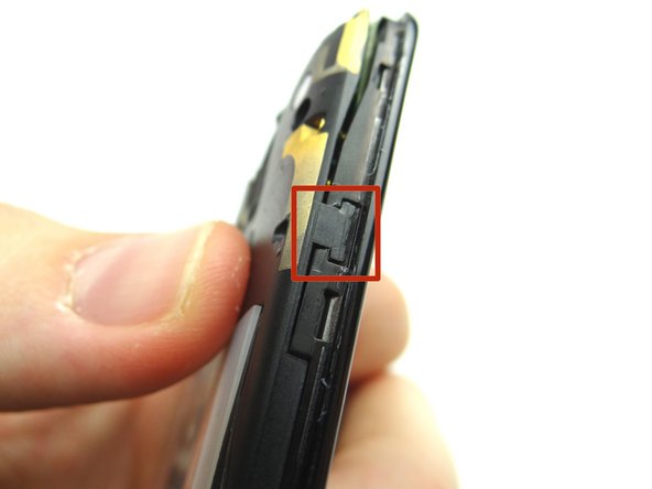
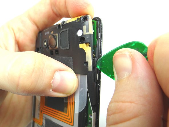
  8. Use the guitar pick to free the marked clip while pulling the top edge of the panel with your finger Use the guitar pick to free the marked clip while pulling the top edge of the panel with your finger
    • Use the guitar pick to free the marked clip while pulling the top edge of the panel with your finger

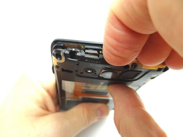
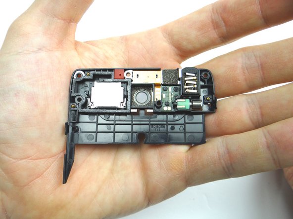
  9. Pull the top panel free with your fingers. Place top panel & phone in ZONES II & III.
    • Pull the top panel free with your fingers.

    • Place top panel & phone in ZONES II & III.

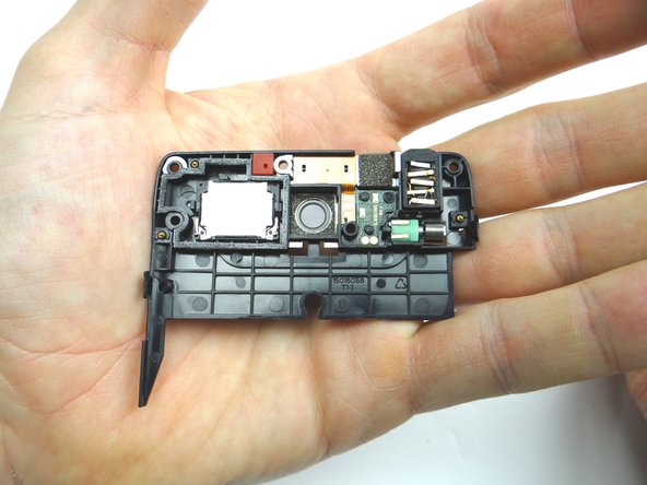
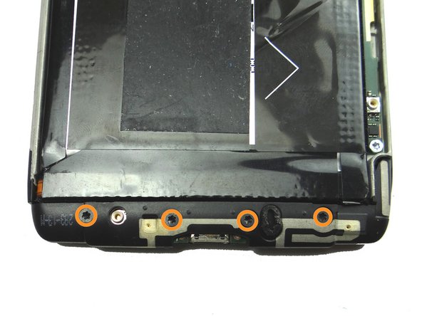
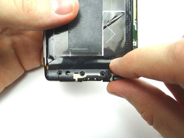
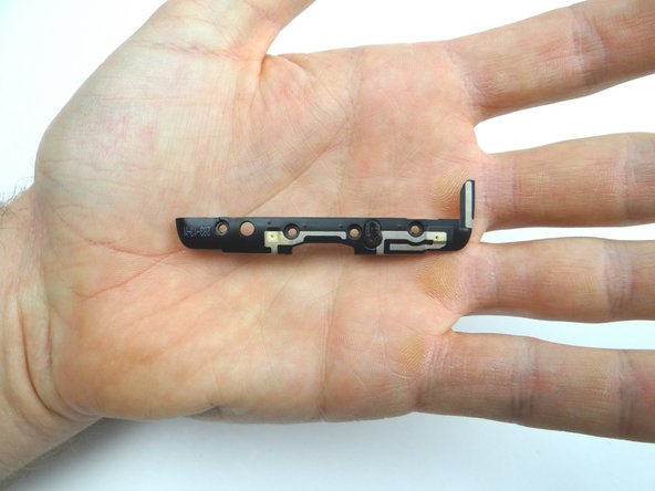
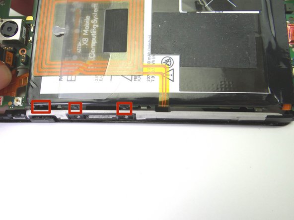
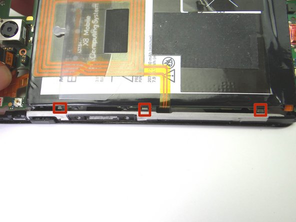
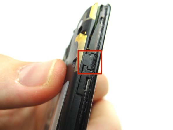
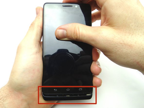
  10. Picture 1: Remove four 4.1 mm T5 Torx screws.  Place in SLOT 3. Remove bottom trim with your fingers.  Place in ZONE IV. Remove bottom trim with your fingers.  Place in ZONE IV.
    • Picture 1: Remove four 4.1 mm T5 Torx screws. Place in SLOT 3.

    • Remove bottom trim with your fingers. Place in ZONE IV.

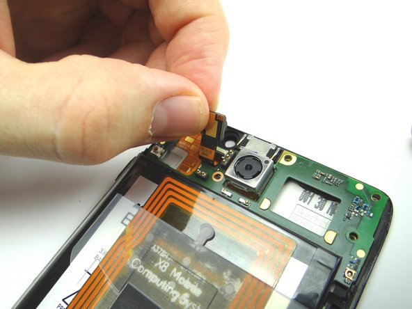
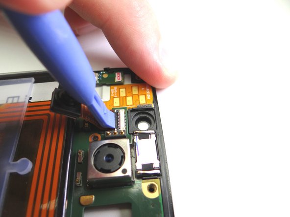
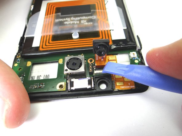
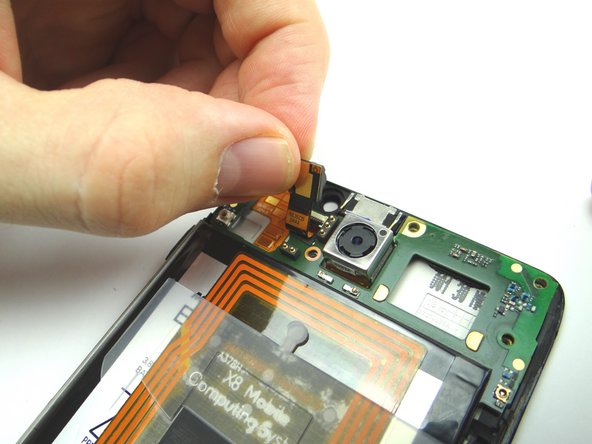
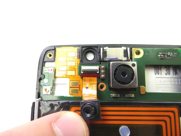
  11. Picture 1: Gently pull front-facing camera up from its socket, but don't try to remove it! Pictures 2: Fold back the front-facing camera to access the ZIF connector. Picture 3: Use the blue pry tool to lift the black swing bar to open the ZIF connector.
    • Picture 1: Gently pull front-facing camera up from its socket, but don't try to remove it!

    • Pictures 2: Fold back the front-facing camera to access the ZIF connector.

    • Picture 3: Use the blue pry tool to lift the black swing bar to open the ZIF connector.

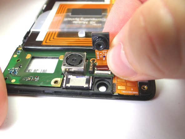
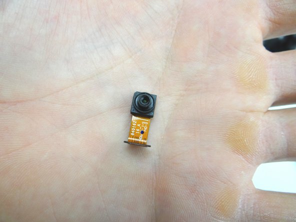
  12. With the ZIF connector open, pull the front-facing camera free. Place in COMPARTMENT C.
    • With the ZIF connector open, pull the front-facing camera free.

    • Place in COMPARTMENT C.

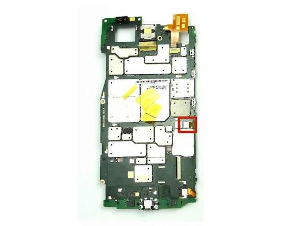
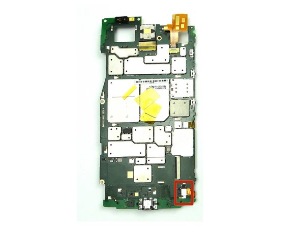
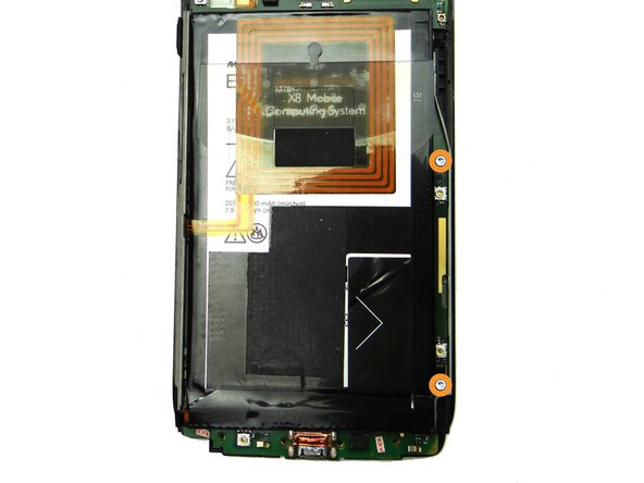
  13. Remove two silver 2.7 mm T5 Torx screws on right side of logic board.  Place in SLOT 4.
    • Remove two silver 2.7 mm T5 Torx screws on right side of logic board. Place in SLOT 4.

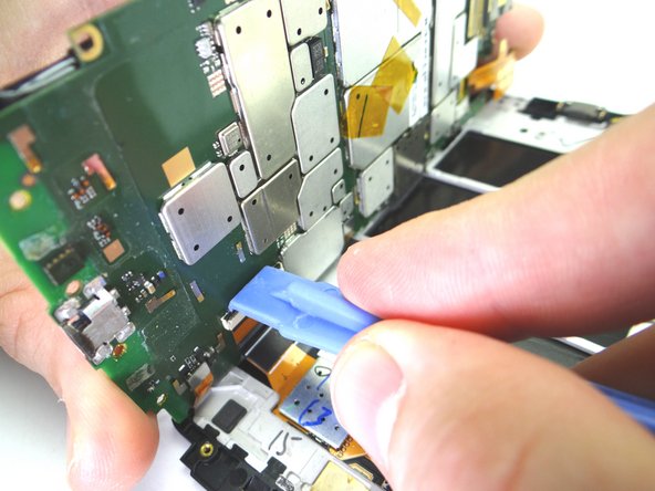
  14. Picture 1: Insert the flat end of the spudger in the upper-right corner between the logic board and display assembly.  Lift up and grab the top of the logic board with your fingers. Picture 2: While holding up the top of the logic board with your fingers, pry up right side with the blue pry tool. Picture 3: Continue opening the right side of the logic board away from the display assembly like a book until it reaches nearly a 90 degree angle.
    • Picture 1: Insert the flat end of the spudger in the upper-right corner between the logic board and display assembly. Lift up and grab the top of the logic board with your fingers.

    • Picture 2: While holding up the top of the logic board with your fingers, pry up right side with the blue pry tool.

    • Picture 3: Continue opening the right side of the logic board away from the display assembly like a book until it reaches nearly a 90 degree angle.

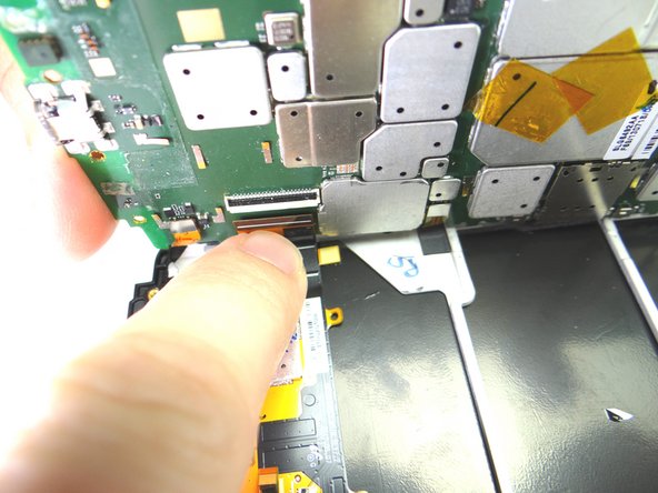
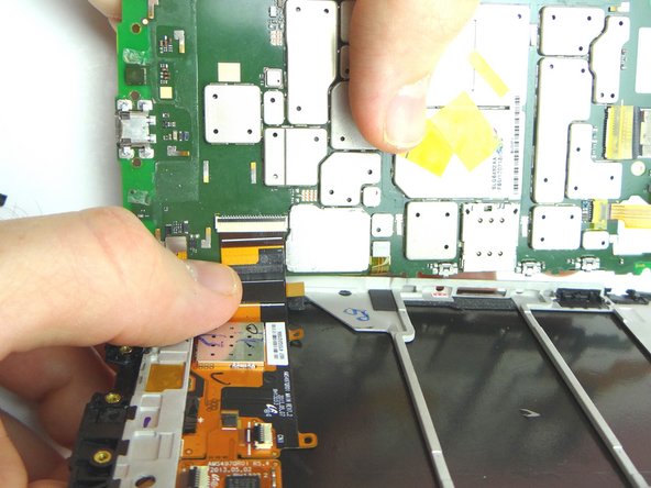
  15. Pictures 1 & 2: Use the blue pry tool to open the black swing bar of the display cable ZIF connector. Picture 3: Pull the display cable free with your finger. Picture 3: Pull the display cable free with your finger.
    • Pictures 1 & 2: Use the blue pry tool to open the black swing bar of the display cable ZIF connector.

    • Picture 3: Pull the display cable free with your finger.

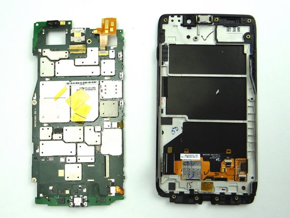
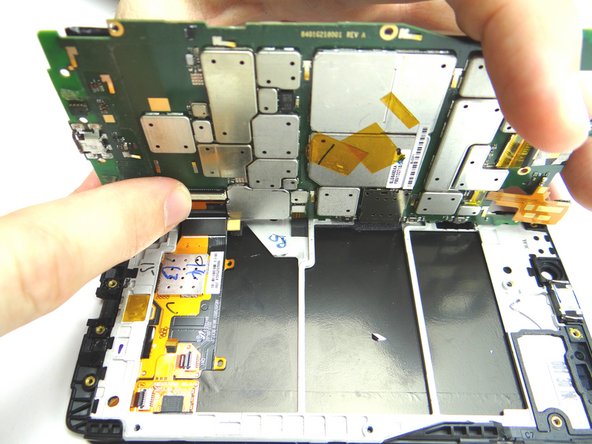
  16. Separate the logic board from the display assembly.
    • Separate the logic board from the display assembly.

    • Place logic board and display assembly in ZONE V.

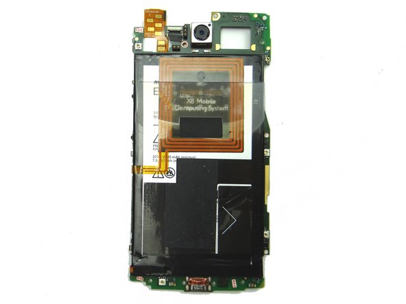
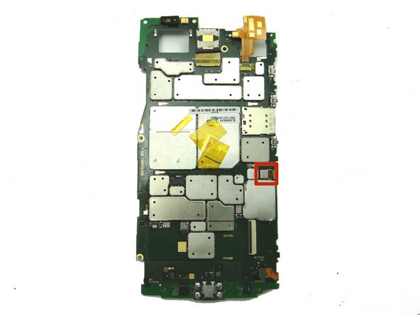
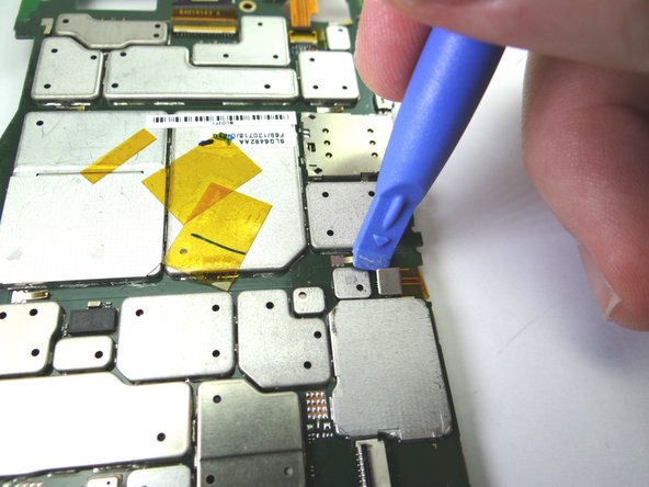
  17. Turn logic board over so the battery is face down. Use blue pry tool to disconnect antenna cable. Use blue pry tool to disconnect antenna cable.
    • Turn logic board over so the battery is face down.

    • Use blue pry tool to disconnect antenna cable.

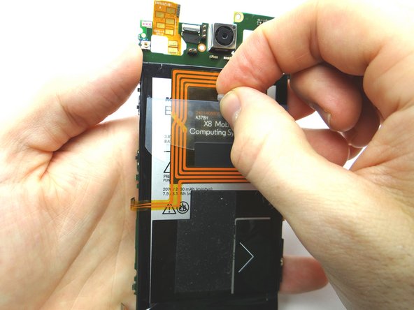
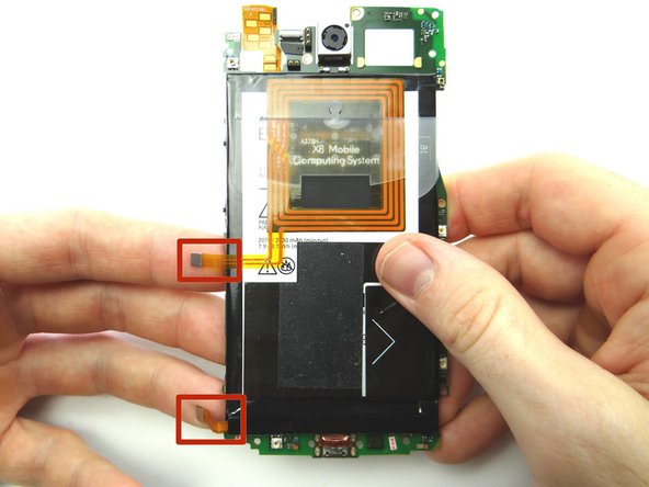
  18. Disconnect battery cable. Pull on battery tab until there's enough space to pull on the battery with your finger. Pull on the battery with your finger.
    • Disconnect battery cable.

    • Pull on battery tab until there's enough space to pull on the battery with your finger.

    • Pull on the battery with your finger.

  19. Picture 1: Seat battery and wrap antenna and battery cables around to the underside of the logic board. Picture 2: Seat antenna cable with your finger. Picture 3: Seat battery cable with your finger.
    • Picture 1: Seat battery and wrap antenna and battery cables around to the underside of the logic board.

    • Picture 2: Seat antenna cable with your finger.

    • Picture 3: Seat battery cable with your finger.

  20. Seat the display cable in the ZIF connector.  Push the cable in until the white line is barely showing. Close the ZIF connector black bar.
    • Seat the display cable in the ZIF connector. Push the cable in until the white line is barely showing.

    • Close the ZIF connector black bar.

  21. Picture 1: Fold the logic board down onto the display assembly. Picture 2: Make sure the power and volume tabs on the logic board align with the sockets on the display assembly. Picture 3: The logic board tabs will align too.
    • Picture 1: Fold the logic board down onto the display assembly.

    • Picture 2: Make sure the power and volume tabs on the logic board align with the sockets on the display assembly.

    • Picture 3: The logic board tabs will align too.

  22. Replace two silver 2.7 mm T5 Torx screws on right side of logic board from SLOT 4.
    • Replace two silver 2.7 mm T5 Torx screws on right side of logic board from SLOT 4.

  23. Retrieve front-facing camera from COMPARTMENT C. Push camera cable into ZIF connector. Close ZIF connector with blue pry tool.
    • Retrieve front-facing camera from COMPARTMENT C.

    • Push camera cable into ZIF connector.

    • Close ZIF connector with blue pry tool.

  24. Push front-facing camera back into its socket.
    • Push front-facing camera back into its socket.

  25. Retrieve bottom trim from ZONE IV.  Seat it at the bottom of the phone. Picture 3: Replace four 4.1 mm T5 Torx screws from SLOT 3. Picture 3: Replace four 4.1 mm T5 Torx screws from SLOT 3.
    • Retrieve bottom trim from ZONE IV. Seat it at the bottom of the phone.

    • Picture 3: Replace four 4.1 mm T5 Torx screws from SLOT 3.

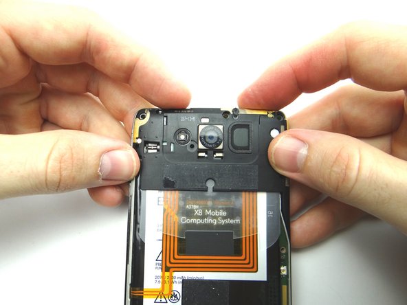
  26. Seat top panel at the top of the phone. Push the marked clip into place. Push the marked clip into place.
    • Seat top panel at the top of the phone.

    • Push the marked clip into place.

  27. Picture 1: Replace four 4.1 mm T5 Torx screws from SLOT 2. Picture 2: Replace 6.3 mm T3 Torx screw near the lower-left edge of the camera from SLOT 1.
    • Picture 1: Replace four 4.1 mm T5 Torx screws from SLOT 2.

    • Picture 2: Replace 6.3 mm T3 Torx screw near the lower-left edge of the camera from SLOT 1.

  28. Retrieve battery cover from ZONE I. Slide front panel into the bottom of the battery cover. Slide front panel into the bottom of the battery cover.
    • Retrieve battery cover from ZONE I.

    • Slide front panel into the bottom of the battery cover.

  29. Push top of battery cover onto front panel. Push top of battery cover onto front panel.
    • Push top of battery cover onto front panel.

  30. Squeeze the sides into place. Make sure there are no gaps, especially near the opening for the SIM card tray. Make sure there are no gaps, especially near the opening for the SIM card tray.
    • Squeeze the sides into place.

    • Make sure there are no gaps, especially near the opening for the SIM card tray.

  31. Replace SIM card tray from COMPARTMENT A. Power up and test replacement part or parts. Power up and test replacement part or parts.
    • Replace SIM card tray from COMPARTMENT A.

    • Power up and test replacement part or parts.

Finish Line
James Linder

Member since: 01/24/2013

71,591 Reputation

217 Guides authored

0 Comments

Add Comment

View Statistics:

Past 24 Hours: 0

Past 7 Days: 0

Past 30 Days: 1

All Time: 49

CELL PHONE SANDBOX