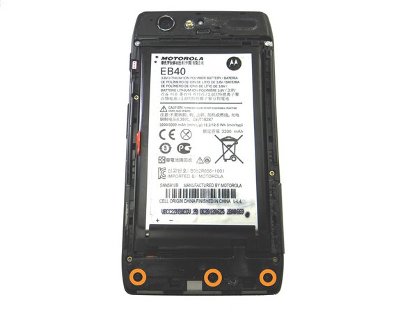
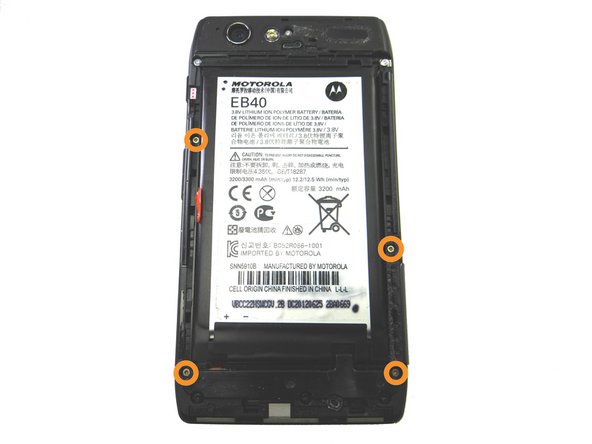
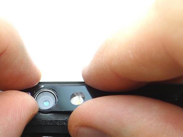
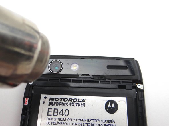
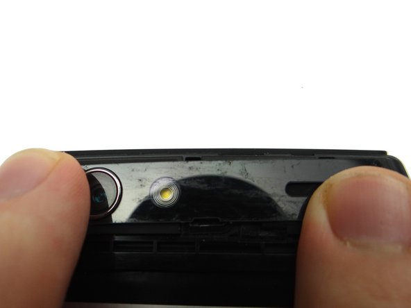
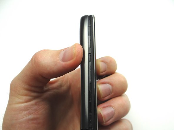
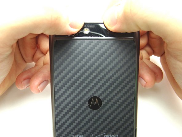
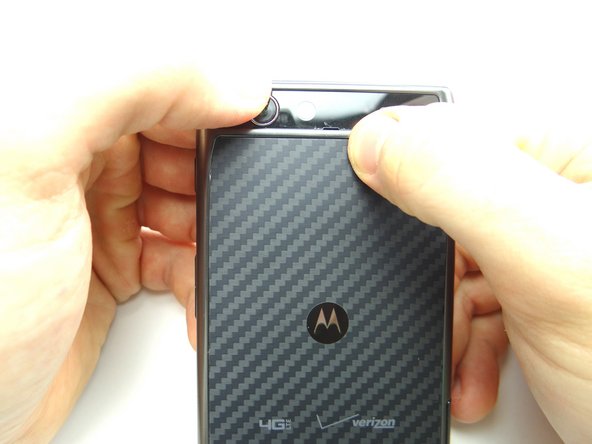
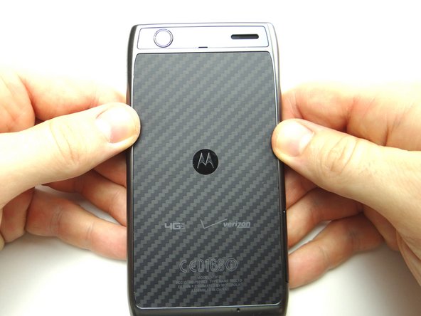
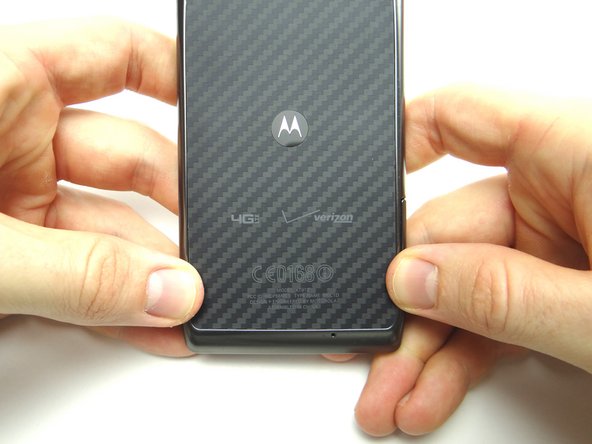
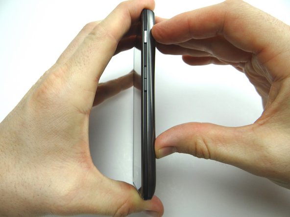
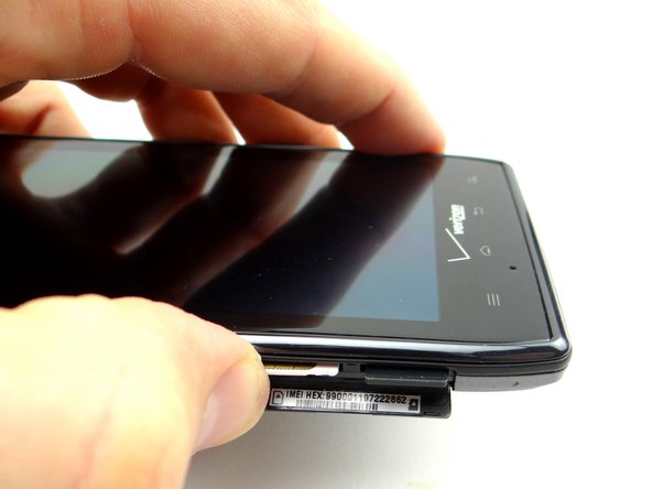
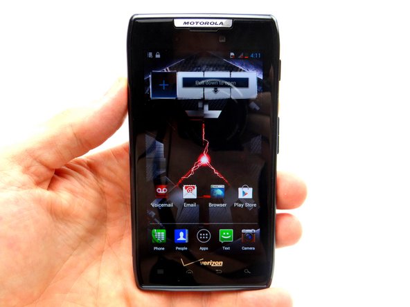
1. Before disassembly, thoroughly wash and dry your hands. Power down the device.
    • Before disassembly, thoroughly wash and dry your hands.

    • Power down the device.

    • Remove the SIM card and SD card: push card in and it will pop out. Place both in COMPARTMENT A.

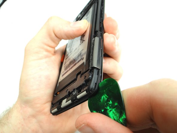
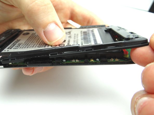
  2. Picture 1: Use the guitar pick to gently pry between the battery cover and front panel. Run the pick around the entire perimeter of the phone to release clips securing the battery cover. Picture 2: Adhesive holds the battery cover in place.  Continue peeling the battery cover up with your fingers until it reaches the amount of separation seen in the picture.  You'll begin to feel tension from the adhesive when you reach to correct amount of separation.
    • Picture 1: Use the guitar pick to gently pry between the battery cover and front panel.

    • Run the pick around the entire perimeter of the phone to release clips securing the battery cover.

    • Picture 2: Adhesive holds the battery cover in place. Continue peeling the battery cover up with your fingers until it reaches the amount of separation seen in the picture. You'll begin to feel tension from the adhesive when you reach to correct amount of separation.

    • Work your way around the entire perimeter of the phone.

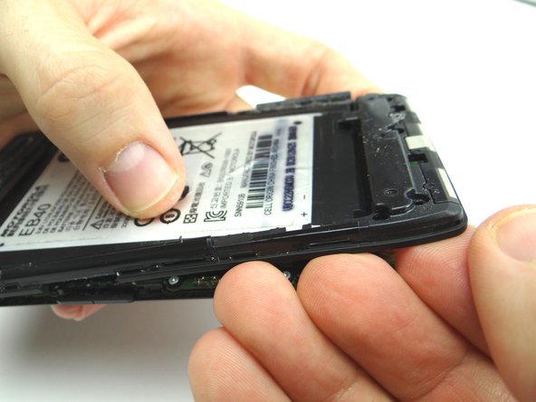
    • Picture 3: Run the guitar pick between the battery cover and rear camera trim to release final clips (red square).

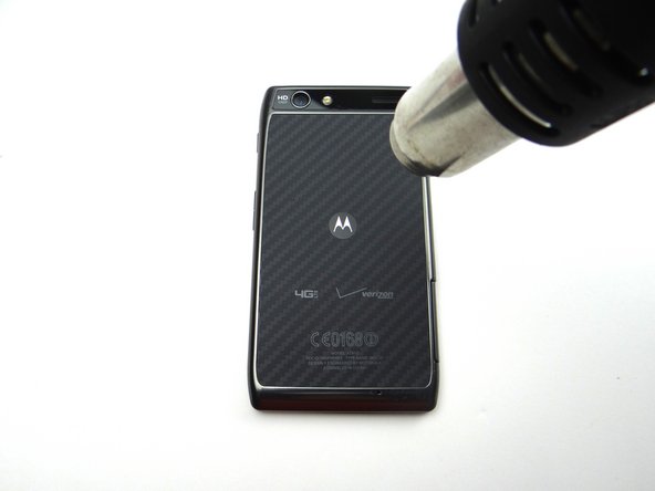
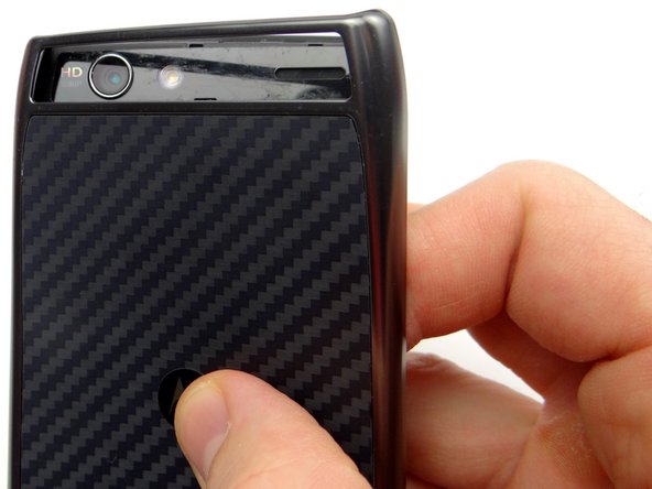
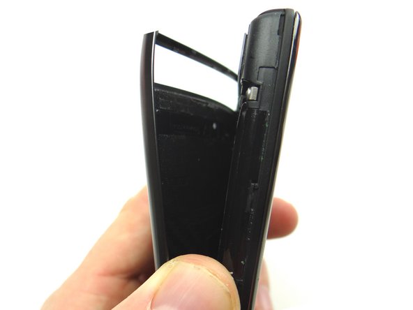
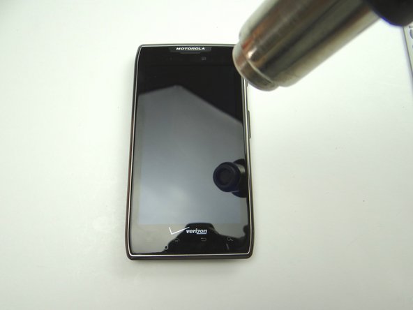
  3. Picture 1: Apply low-level heat (100° Celcius) all over the back of the phone for 60 seconds to loosen the adhesive securing the battery cover.  Apply heat to the Motorola symbol in the middle for an additional 15 seconds. Picture 2: Use your fingers to gently peel the battery cover from the phone. Take care when peeling up the Motorola symbol - it has a tendency to stay stuck to the battery.
    • Picture 1: Apply low-level heat (100° Celcius) all over the back of the phone for 60 seconds to loosen the adhesive securing the battery cover. Apply heat to the Motorola symbol in the middle for an additional 15 seconds.

    • Picture 2: Use your fingers to gently peel the battery cover from the phone.

    • Take care when peeling up the Motorola symbol - it has a tendency to stay stuck to the battery.

    • Picture 3: Finish removing the battery cover, noting the battery cover is fairly flexible.

    • Place battery cover in ZONE I.

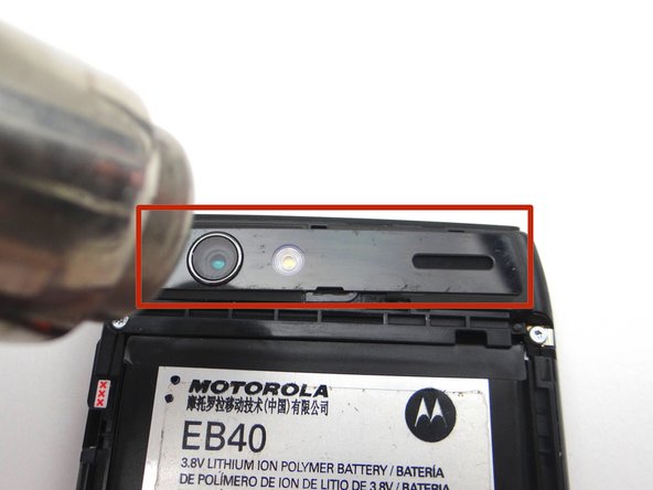
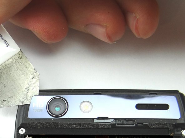
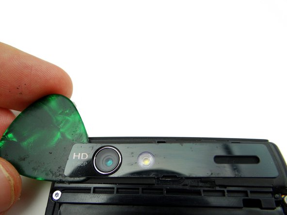
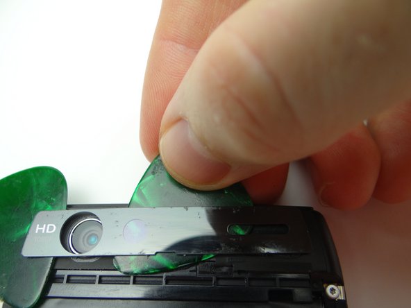
  4. Picture 1: Apply low-level heat (100° Celcius) to the Camera Trim for 30 seconds. Picture 2: Wedge the iSesamo under the upper-left corner of the rear camera trim. Picture 3: Replace the iSesamo with a guitar pick.
    • Picture 1: Apply low-level heat (100° Celcius) to the Camera Trim for 30 seconds.

    • Picture 2: Wedge the iSesamo under the upper-left corner of the rear camera trim.

    • Picture 3: Replace the iSesamo with a guitar pick.

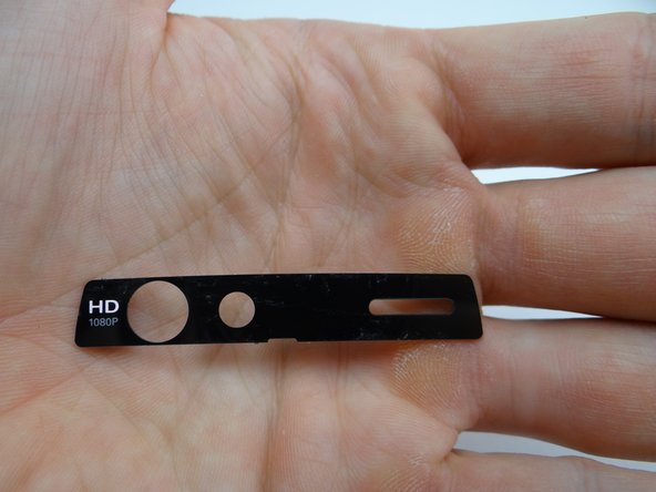
  5. Picture 1: Use a guitar pick to peel up the right side. If you encounter resistance, apply more heat. Picture 2: Once the rear camera trim is completely free, place in COMPARTMENT C.
    • Picture 1: Use a guitar pick to peel up the right side. If you encounter resistance, apply more heat.

    • Picture 2: Once the rear camera trim is completely free, place in COMPARTMENT C.

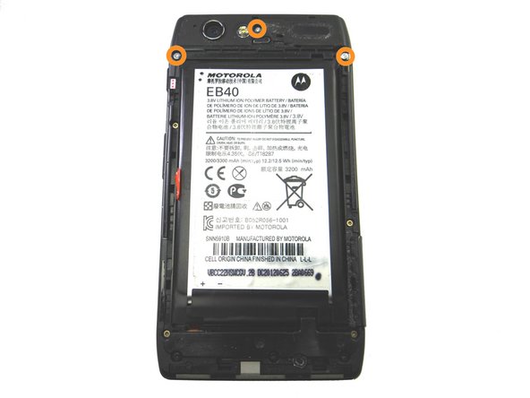
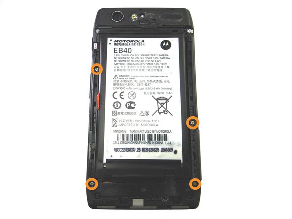
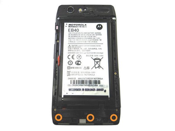
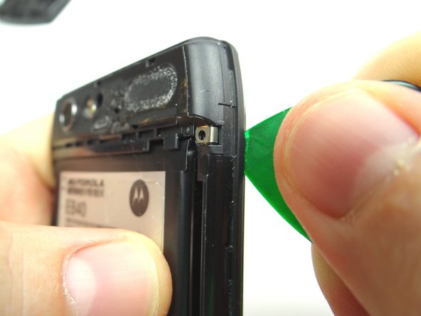
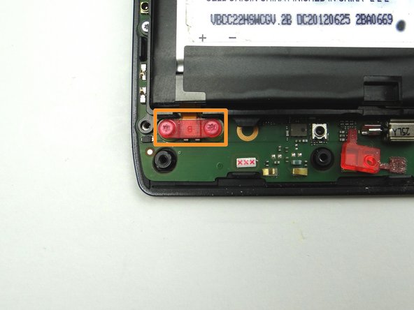
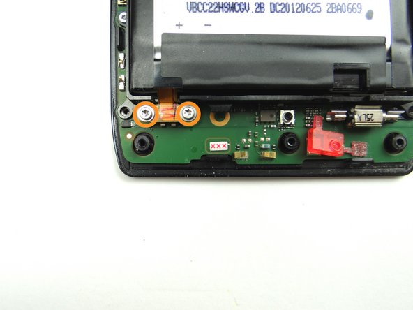
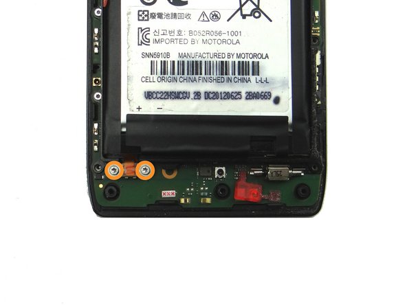
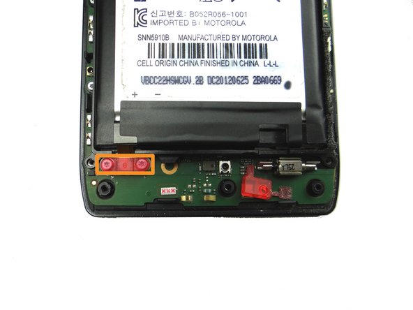
  6. Remove three 6.7 mm silver T3 Torx screws and place into SLOT 1. Remove four 4.0 mm gold T3 Torx screws and place into SLOT 2. Remove three 4.5 mm black T5 Torx screws and place into SLOT 3.
    • Remove three 6.7 mm silver T3 Torx screws and place into SLOT 1.

    • Remove four 4.0 mm gold T3 Torx screws and place into SLOT 2.

    • Remove three 4.5 mm black T5 Torx screws and place into SLOT 3.

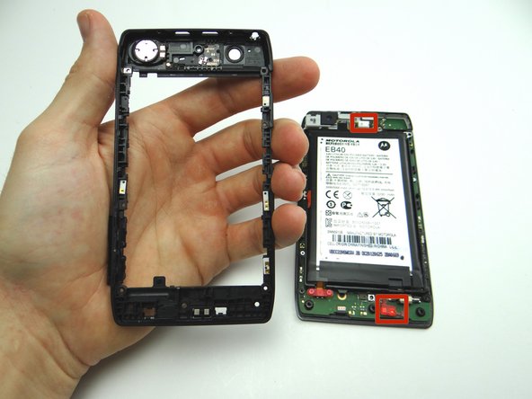
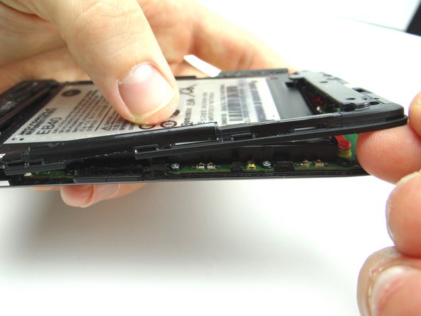
  7. With the phone face down wedge the guitar pick between the display and mid-frame in the upper-right corner.  Run the guitar pick down the right side to release clips holding mid-frame to the display. With the phone face down wedge the guitar pick between the display and mid-frame in the upper-right corner.  Run the guitar pick down the right side to release clips holding mid-frame to the display.
    • With the phone face down wedge the guitar pick between the display and mid-frame in the upper-right corner. Run the guitar pick down the right side to release clips holding mid-frame to the display.

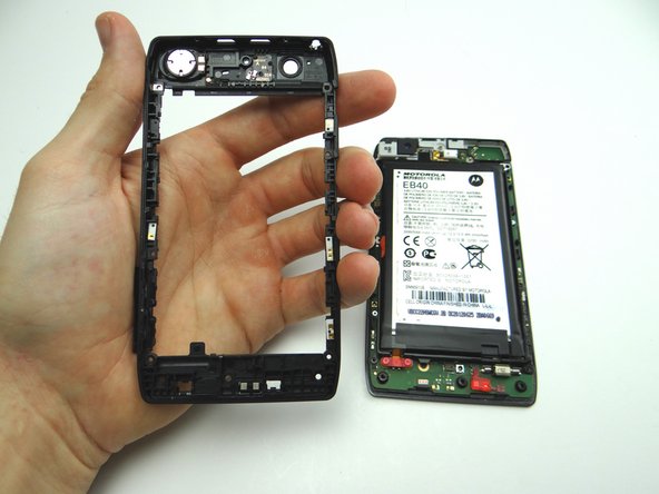
  8. Use your fingers to continue peeling the remaining clips holding the mid-frame to the display. Place the mid-frame into ZONE II. Place the mid-frame into ZONE II.
    • Use your fingers to continue peeling the remaining clips holding the mid-frame to the display.

    • Place the mid-frame into ZONE II.

  9. Picture 1: Remove the rubber screw cover and place into SLOT 4. Picture 2: Remove two 3.3 mm T5 Torx screws and place into SLOT 5.
    • Picture 1: Remove the rubber screw cover and place into SLOT 4.

    • Picture 2: Remove two 3.3 mm T5 Torx screws and place into SLOT 5.

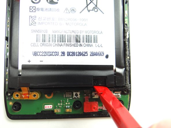
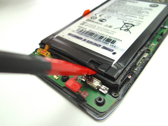
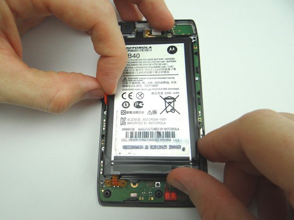
  10. Picture 1: Apply low-level heat (100° Celsius) to the screen to loosen adhesive holding the battery in place. Pictures 2 & 3: Wedge spudger underneath the notch in the battery in the lower-right corner and pry up. Pry up around the edges to free the adhesive holding down the battery.
    • Picture 1: Apply low-level heat (100° Celsius) to the screen to loosen adhesive holding the battery in place.

    • Pictures 2 & 3: Wedge spudger underneath the notch in the battery in the lower-right corner and pry up.

    • Pry up around the edges to free the adhesive holding down the battery.

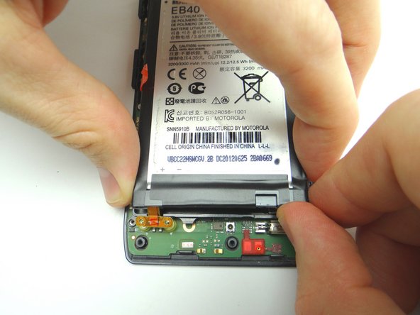
  11. Remove the battery starting in the lower-right corner. Use the battery removal tab to finish removing the battery once it's nearly free.  Place it in ZONE III.
    • Remove the battery starting in the lower-right corner.

    • Use the battery removal tab to finish removing the battery once it's nearly free. Place it in ZONE III.

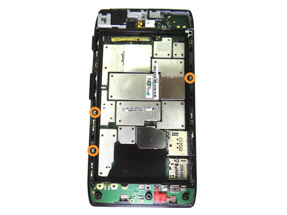
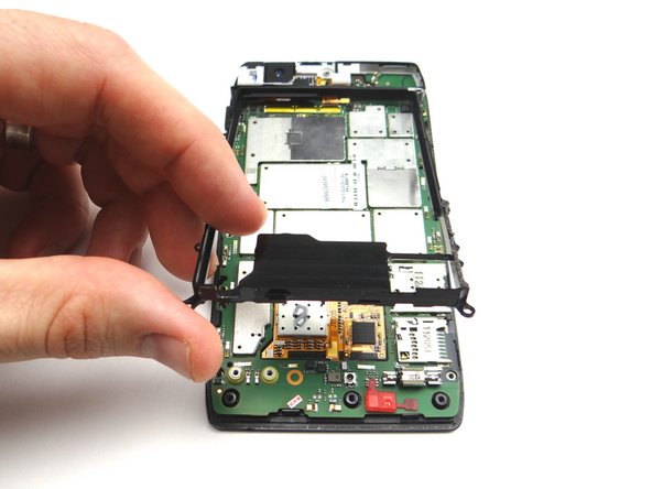
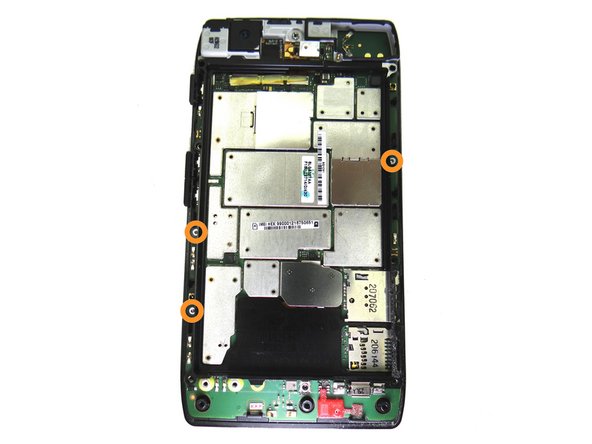
  12. Remove three 2.5 mm T3 Torx screws and place in SLOT 6. Lift the metal chassis from the logic board. Place in ZONE IV.
    • Remove three 2.5 mm T3 Torx screws and place in SLOT 6.

    • Lift the metal chassis from the logic board. Place in ZONE IV.

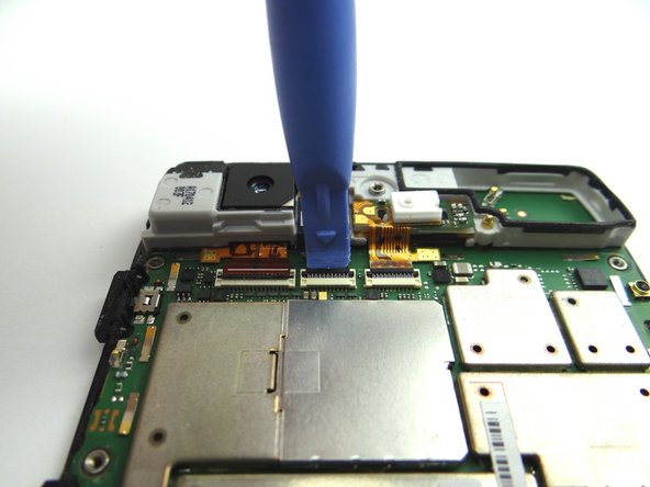
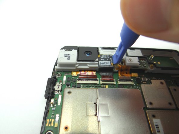
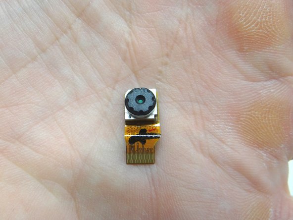
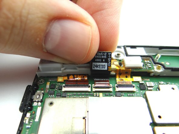
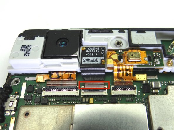
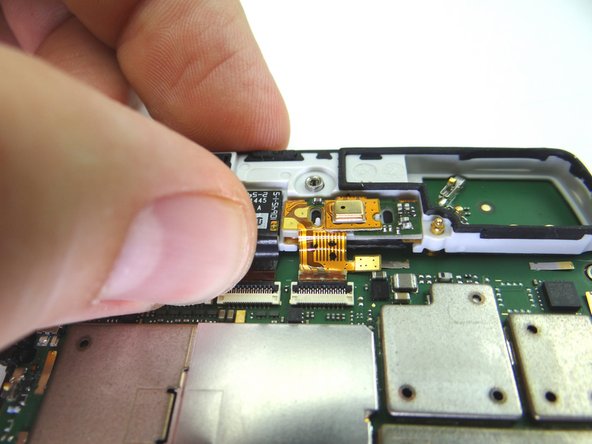
  13. Picture 1: Place blue pry tool under black swing bar of ZIF connector and lift up to open it. Picture 2: With the ZIF connector in the open/up position, lift the front-facing camera out of its socket with the blue pry tool. Picture 3: Pull the cable free with your fingers and remove the front-facing camera. Place it in COMPARTMENT D.
    • Picture 1: Place blue pry tool under black swing bar of ZIF connector and lift up to open it.

    • Picture 2: With the ZIF connector in the open/up position, lift the front-facing camera out of its socket with the blue pry tool.

    • Picture 3: Pull the cable free with your fingers and remove the front-facing camera. Place it in COMPARTMENT D.

  14. Picture 1: Replace front-facing camera from COMPARTMENT D.  Push the cable into the connector first, then seat the camera in its socket. Picture 2: The white line on the camera cable should line up with the top edge of the connector. Close black ZIF connector bar with your finger.
    • Picture 1: Replace front-facing camera from COMPARTMENT D. Push the cable into the connector first, then seat the camera in its socket.

    • Picture 2: The white line on the camera cable should line up with the top edge of the connector.

    • Close black ZIF connector bar with your finger.

  15. Seat the metal chassis on the logic board from ZONE IV. Replace three 2.5 mm T3 Torx screws and from SLOT 6.
    • Seat the metal chassis on the logic board from ZONE IV.

    • Replace three 2.5 mm T3 Torx screws and from SLOT 6.

  16. Picture 1: Retrieve battery from ZONE III. Place the battery into the metal chassis frame. Picture 2: Replace two 3.3 mm T5 Torx screws from SLOT 5. Picture 3: Replace the rubber screw cover from SLOT 4.
    • Picture 1: Retrieve battery from ZONE III. Place the battery into the metal chassis frame.

    • Picture 2: Replace two 3.3 mm T5 Torx screws from SLOT 5.

    • Picture 3: Replace the rubber screw cover from SLOT 4.

  17. Seat the mid-frame from ZONE II on the display assembly. CHECK PLACEMENT OF MIC COVERS.
    • Seat the mid-frame from ZONE II on the display assembly.

    • CHECK PLACEMENT OF MIC COVERS.

    • Secure the clips: Snap the top of the mid-frame into place and work your way down.

  18. Picture 1: Replace three 4.5 mm black T5 Torx screws from SLOT 3. Picture 2: Replace four 4.0 mm gold T3 Torx screws from SLOT 2. Picture 3: Replace three 6.7 mm silver T3 Torx screws from SLOT 1.
    • Picture 1: Replace three 4.5 mm black T5 Torx screws from SLOT 3.

    • Picture 2: Replace four 4.0 mm gold T3 Torx screws from SLOT 2.

    • Picture 3: Replace three 6.7 mm silver T3 Torx screws from SLOT 1.

  19. Retrieve the rear camera trim from COMPARTMENT C.  Starting from the left side, reapply the rear camera trim and press firmly to resecure it to the phone. If the trim is loose, try heating the area to reactivate the adhesive.  Apply pressure until the trim is secure.  (If necessary, apply thin strips of double-sided adhesive to secure the trim.) If the trim is loose, try heating the area to reactivate the adhesive.  Apply pressure until the trim is secure.  (If necessary, apply thin strips of double-sided adhesive to secure the trim.)
    • Retrieve the rear camera trim from COMPARTMENT C. Starting from the left side, reapply the rear camera trim and press firmly to resecure it to the phone.

    • If the trim is loose, try heating the area to reactivate the adhesive. Apply pressure until the trim is secure. (If necessary, apply thin strips of double-sided adhesive to secure the trim.)

  20. Picture 1: Replace battery cover from ZONE I. Pictures 2 & 3: Press firmly along the top edge to secure the battery cover. Pictures 2 & 3: Press firmly along the top edge to secure the battery cover.
    • Picture 1: Replace battery cover from ZONE I.

    • Pictures 2 & 3: Press firmly along the top edge to secure the battery cover.

  21. Pictures 1 & 2: Press firmly along all edges of the phone to secure the clips. Picture 3: Run your fingers along all edges to ensure all clips are secured. Picture 3: Run your fingers along all edges to ensure all clips are secured.
    • Pictures 1 & 2: Press firmly along all edges of the phone to secure the clips.

    • Picture 3: Run your fingers along all edges to ensure all clips are secured.

  22. Replace SIM card and SD card from COMPARTMENT A. Power up device and test replaced component or components.
    • Replace SIM card and SD card from COMPARTMENT A.

    • Power up device and test replaced component or components.

Finish Line
James Linder

Member since: 01/24/2013

71,591 Reputation

217 Guides authored

0 Comments

Add Comment

View Statistics:

Past 24 Hours: 0

Past 7 Days: 0

Past 30 Days: 0

All Time: 27

CELL PHONE SANDBOX