-
-
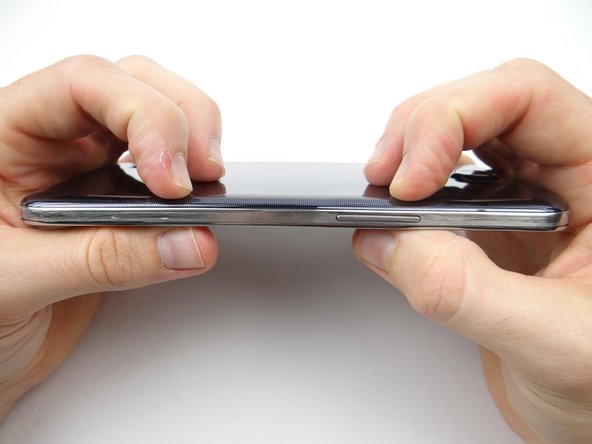
Power down device.
-
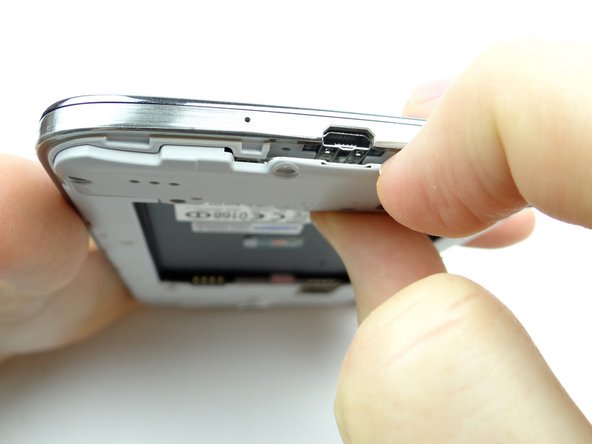
Use the notch above the power button to remove the battery cover. Place in ZONE V.
-
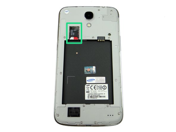
Remove the SIM card and SD card. Place both in Sandbox COMPARTMENT A.
-
-
-
Remove six 3.4 mm #00 Phillips screws from loudspeaker assembly. Place in SLOT 1.
-
Use the curved-tip tweezers to remove any screws that get stuck.
-
-
-
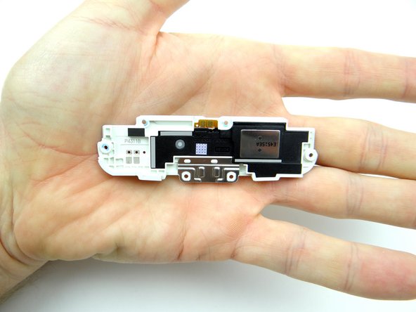
Pull the loudspeaker assembly away from the phone starting near the charging port.
-
Place loudspeaker assembly in ZONE I.
-
-
-
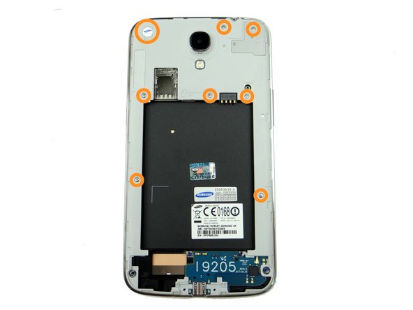
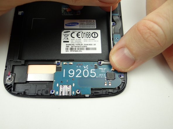
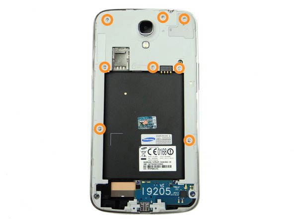
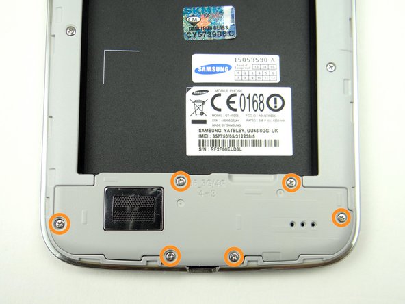
Picture 1: Remove eight 3.4 mm #00 Phillips screws. Place in SLOT 1.
-
Note the Samsung warranty sticker (large circle) in the upper-left corner. Remove it - there's a screw underneath.
-
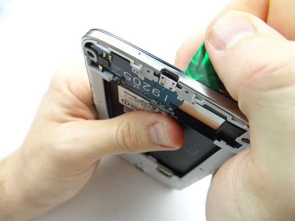
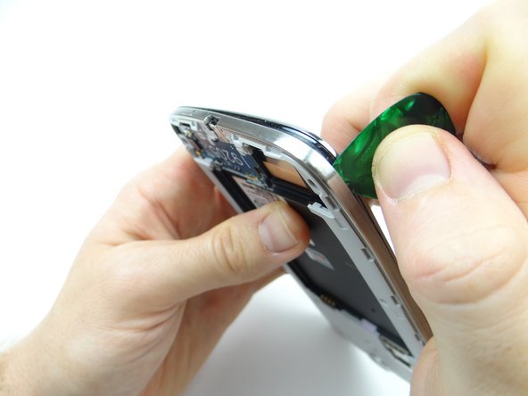
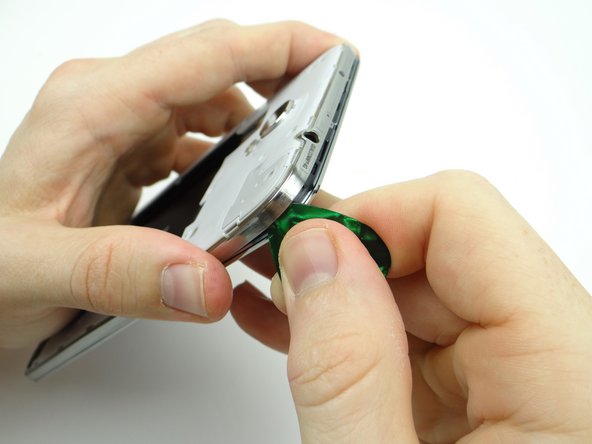
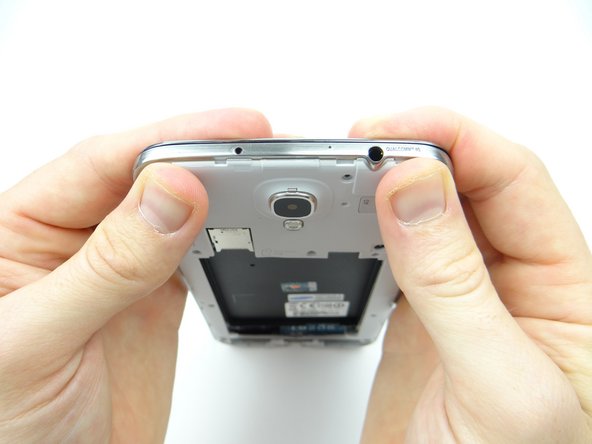
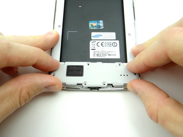
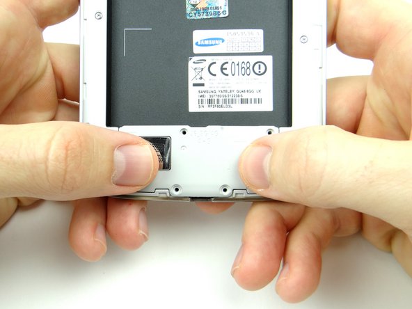
Picture 2: Note the orientation of the phone: insert guitar pick just right of the charging port between the mid-frame and front panel.
-
The mid-frame is thin and weaker under the charging port.
-
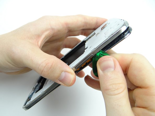
Picture 3: Carefully work your way around the corner to release clips holding the mid-frame.
-
-
-
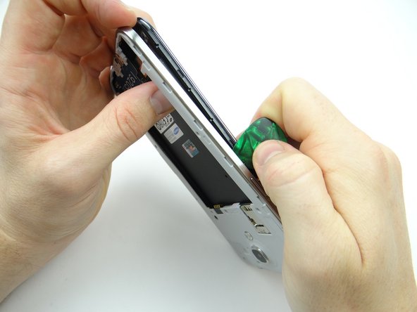
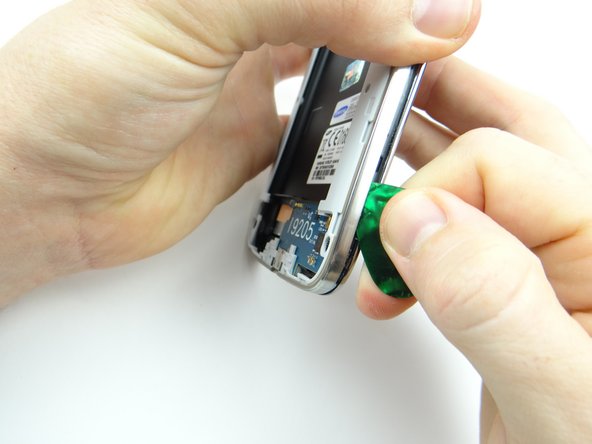
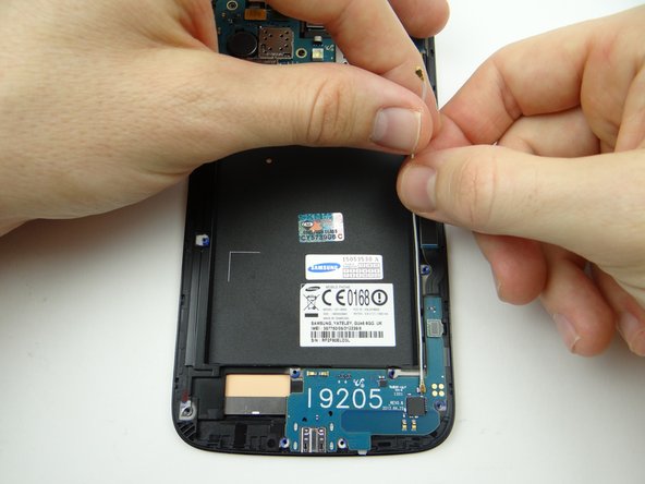
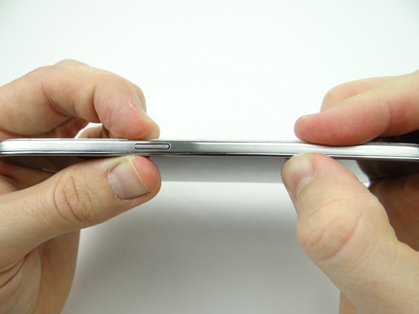
Picture 1: Move up the side of the mid-frame. Remove the guitar pick before you reach the power button.
-
Picture 2: Gently tug on the mid-frame with one hand to create space, then reinsert the guitar pick in the corner above the power button with the opposite hand.
-
Picture 3: Release the clips along the top edge of the mid-frame.
-
-
-
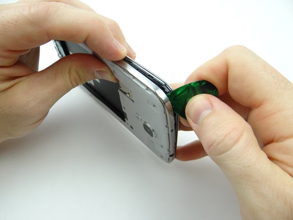
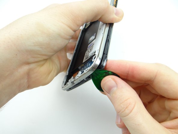
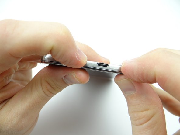
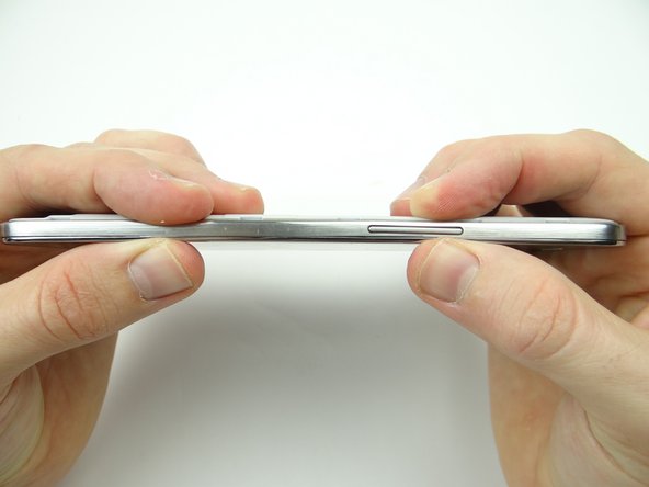
Pictures 1 & 2: Start working your way down the volume rocker side. Remove the guitar pick when you reach the volume rocker.
-
Picture 3: Reinsert the guitar pick below the volume rocker and work your way down.
-
-
-
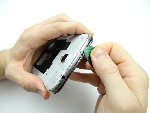
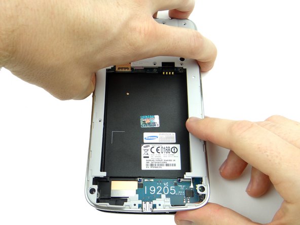
Pictures 1 & 2: Work up the lower-right corner until you're able to wedge your fingers between the mid-frame and front panel.
-
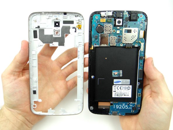
Picture 3: Gently peel the mid-frame away from the front panel. Place mid-frame in ZONE V.
-
The power button and volume rocker are part of the mid-frame assembly.
-
-
-
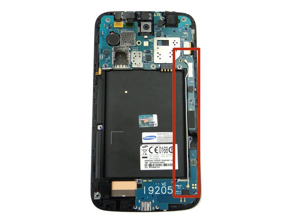
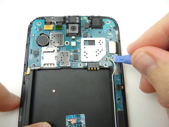
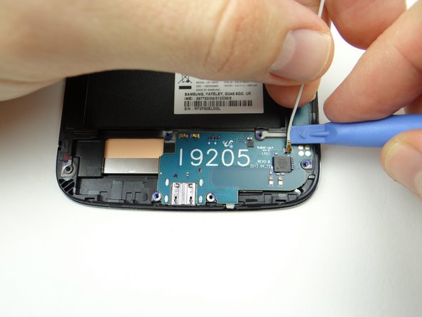
Disconnect the cellular antenna:
-
Use blue pry tool to disconnect top.
-
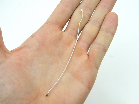
Unthread antenna.
-
-
-
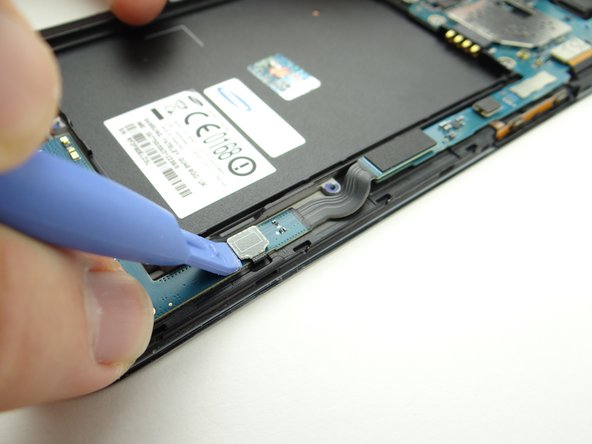
Disconnect bottom.
-
Place antenna in ZONE II.
-
-
-
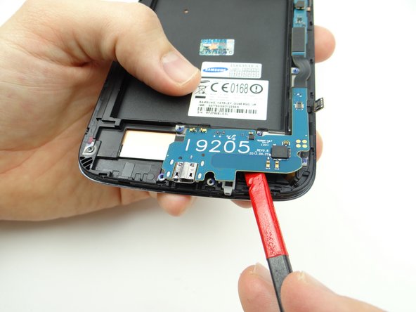
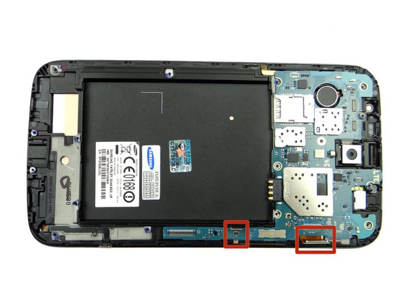
Disconnect the charging port cable.
-
Disconnect soft keys cable.
-
-
-
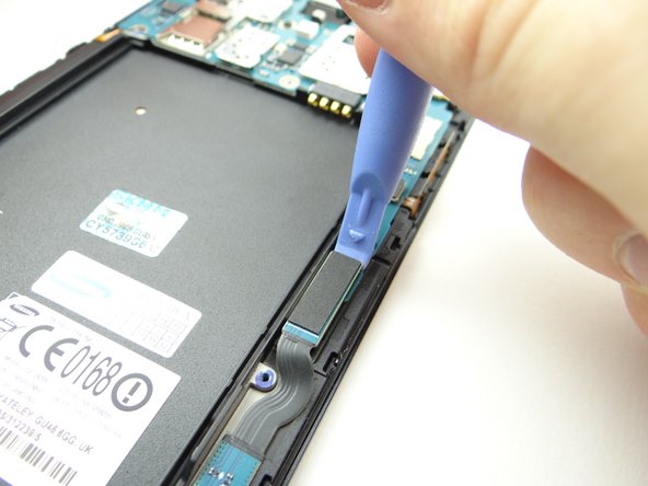
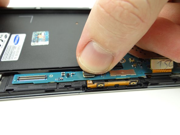
Picture 1: Wedge flat end of spudger exactly where shown and lift slightly.
-
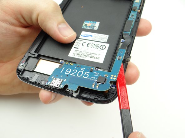
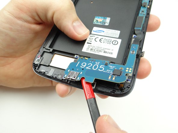
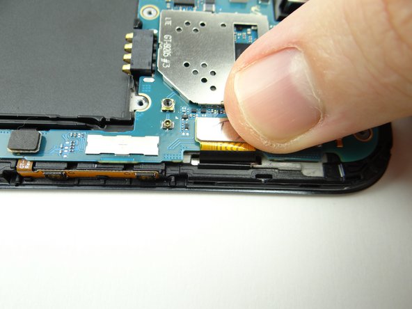
Pictures 2 & 3: Slowly work up the charging port assembly to free it from the mild adhesive holding it in place.
-
-
-
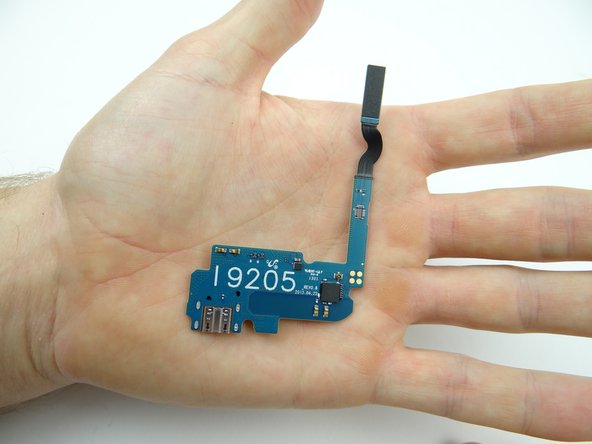
Place charging port in ZONE III.
-
-
-
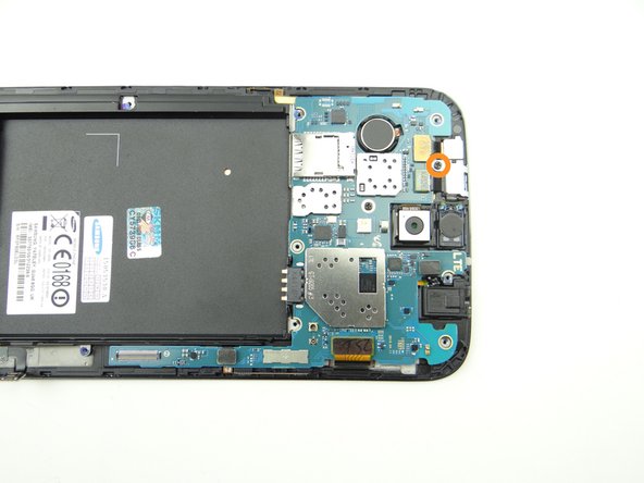
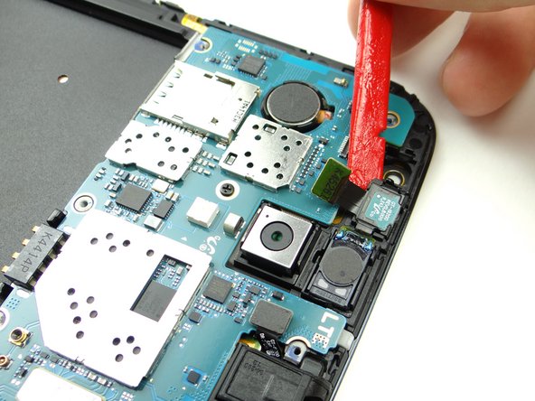
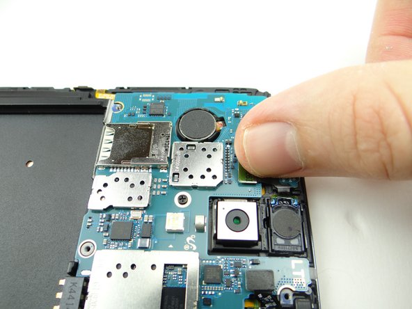
Picture 1: Remove 2.4 mm #00 Phillips screw from shield (covering front-facing camera and infrared sensor). Place in SLOT 2.
-
Picture 2: Avoid contact with the infrared sensor as you remove the shield covering the front camera & speaker:
-
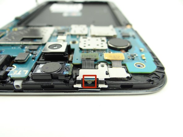
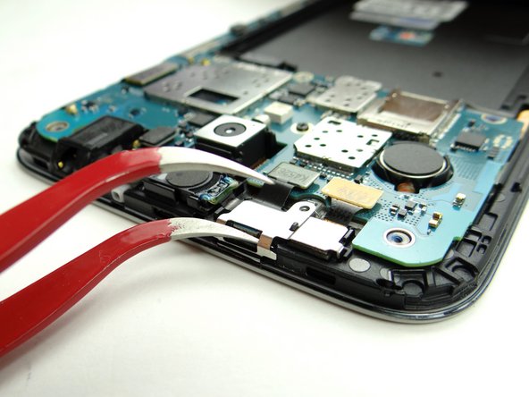
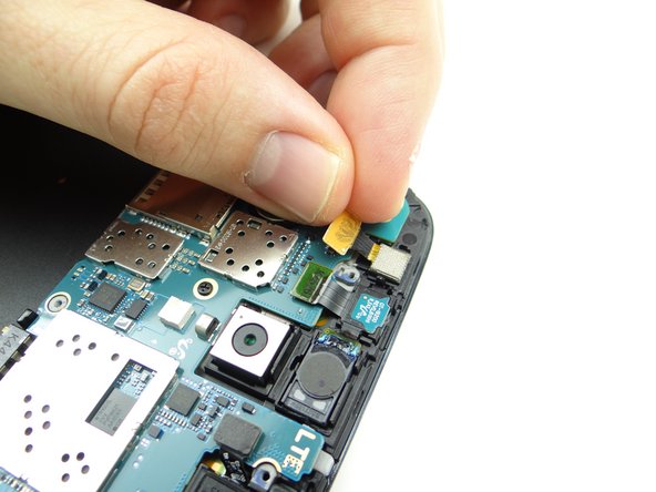
Picture 3: Wedge one prong of the curved-tip tweezers under the shield as shown.
-
-
-
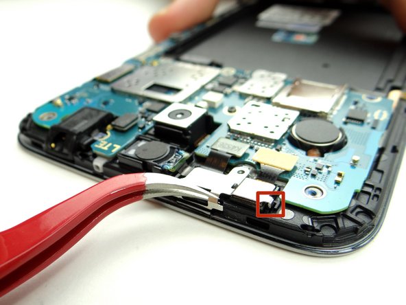
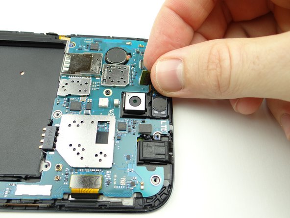
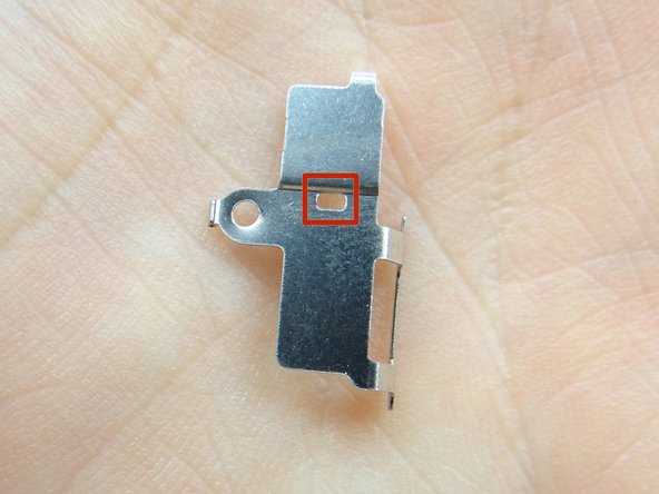
Close tweezers and unhook the tab in the red square first. Continue lifting shield away from phone.
-
Place shield in COMPARTMENT B.
-
-
-
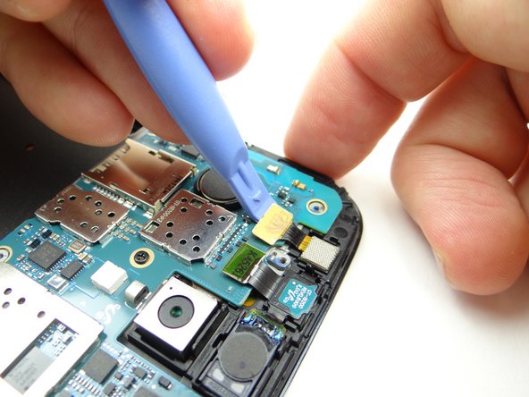
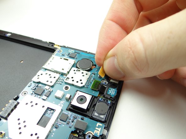
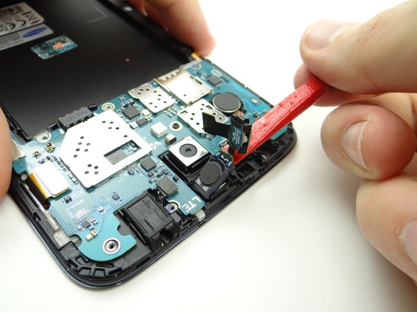
Disconnect front-facing camera with blue pry tool.
-
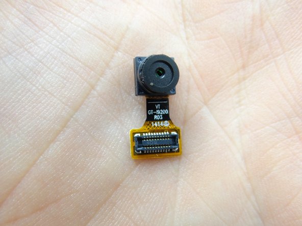
Pick up the camera with your fingers. Place front-facing camera in COMPARTMENT C.
-
-
-
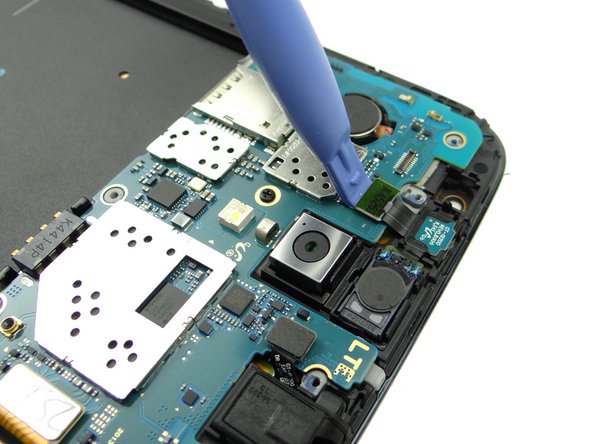
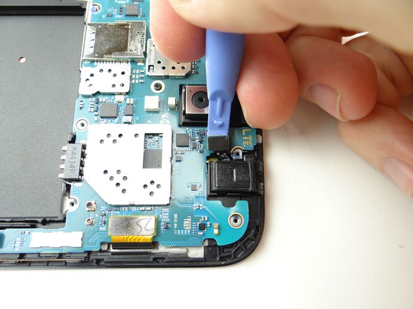
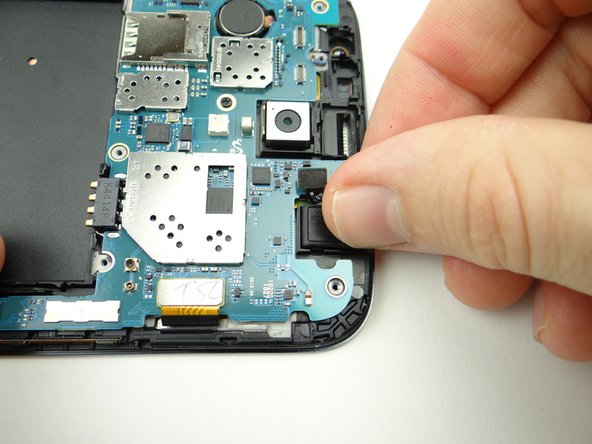
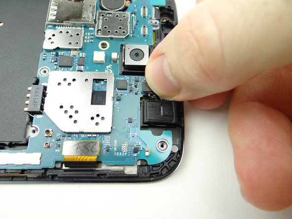
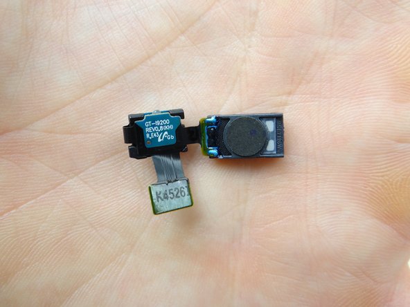
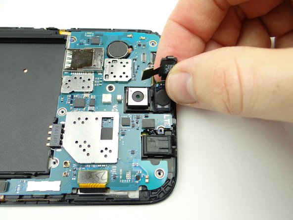
Disconnect infrared sensor / earpiece speaker assembly with blue pry tool.
-
Wedge the flat end of the spudger under the infrared sensor and pry up slightly.
-
-
-
The earpiece speaker is wedged tightly into its slot: use your fingers to carefully peel it up just enough to wedge the spudger underneath.
-
Finish removing the assembly with the flat end of the spudger and place it in COMPARTMENT C.
-
-
-
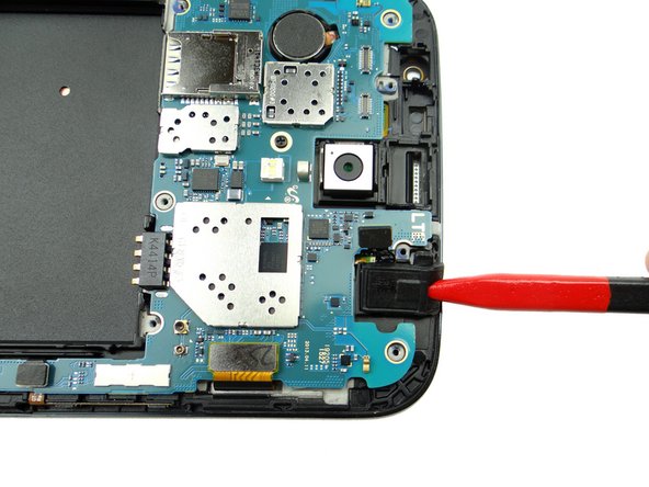
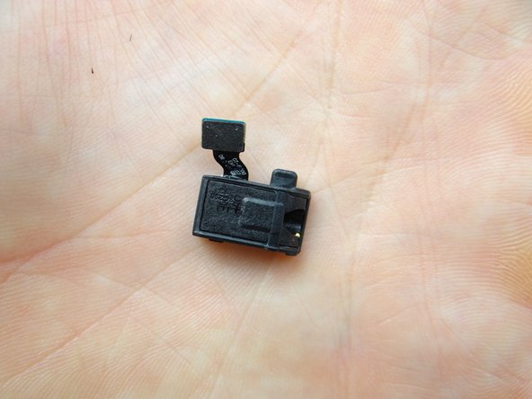
Disconnect the headphone jack.
-
Use the pointed tip of the spudger to lift the headphone jack free.
-
Place headphone jack in COMPARTMENT C.
-
-
-
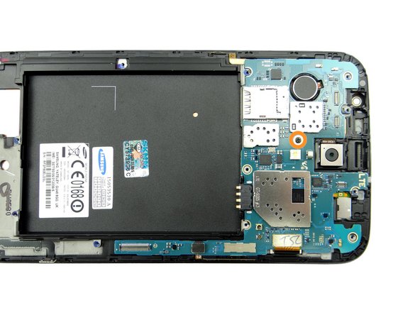
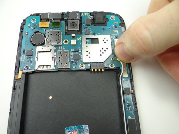
Picture 1: Remove one 2.4 mm #00 Phillips screw. Place in SLOT 2.
-
Picture 2: Disconnect display cable.
-
Picture 3: Disconnect volume rocker cable.
-
-
-
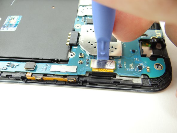
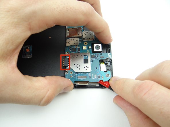
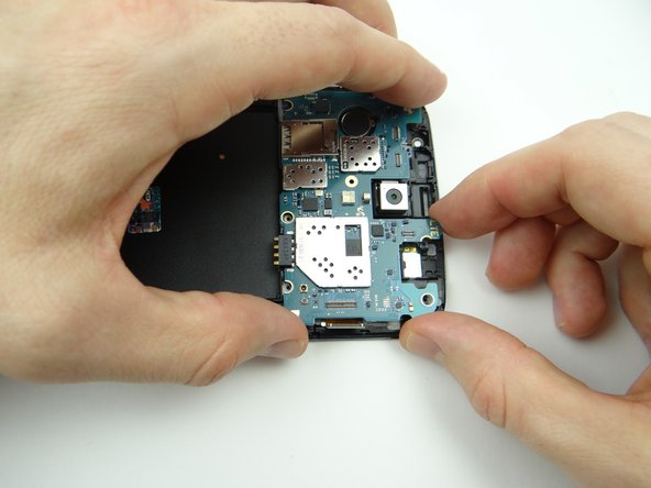
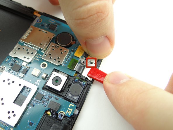
There is a small amount of adhesive under the battery contact (red square in Picture 1):
-
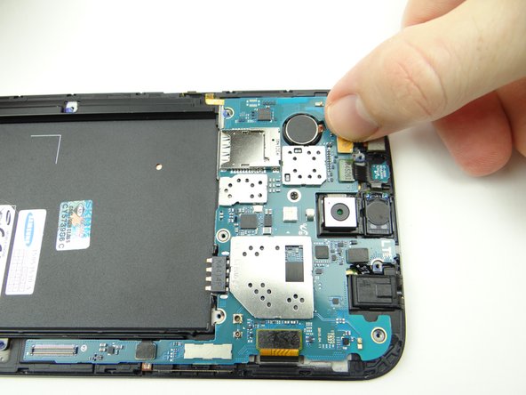
Picture 1: Wedge flat end of the spudger under the corner of the logic board. Slowly twist the spudger to free the adhesive under the battery contact.
-
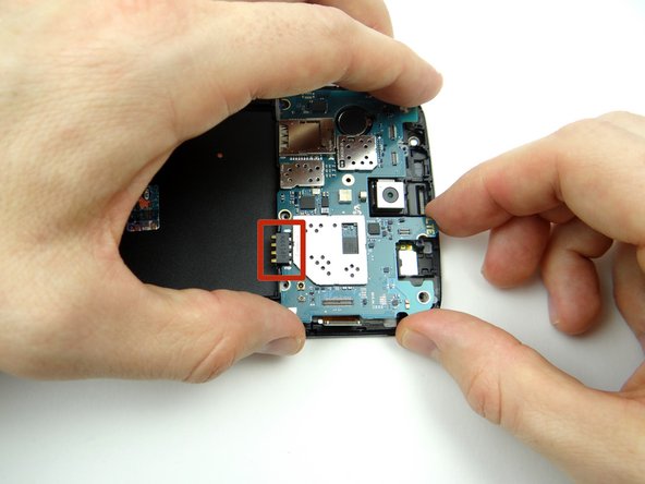
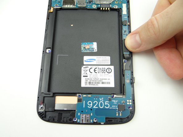
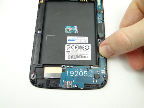
Picture 2: Use both hands to gently guide the logic board away from the front panel.
-
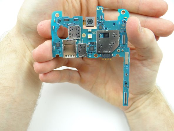
Place logic board in ZONE IV.
-
-
-
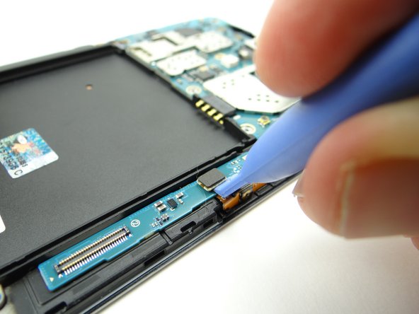
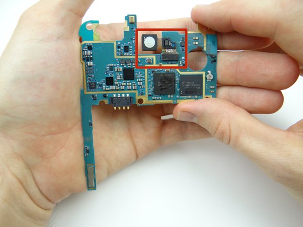
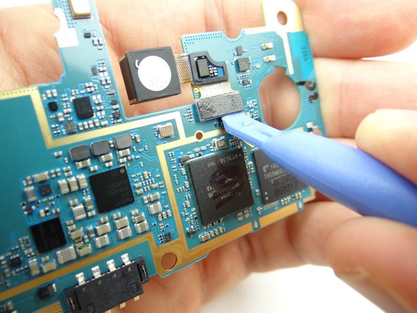
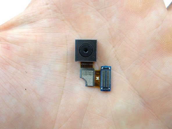
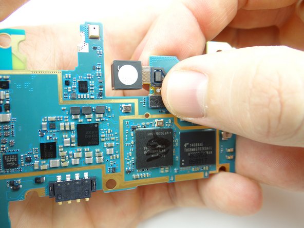
Use a blue pry tool to disconnect the rear camera on the underside of the logic board.
-
Place rear camera in COMPARTMENT D.
-
-
-
From COMPARTMENT D:
-
Seat rear camera on underside of logic board.
-
-
-
From ZONE IV seat the logic board:
-
Make sure the display cable and volume cable aren't trapped underneath.
-
-
-
Picture 1: Connect volume rocker cable.
-
Picture 2: Connect display cable.
-
Picture 3: Replace one 2.4 mm #00 Phillips screw from SLOT 2.
-
-
-
Seat headphone jack from COMPARTMENT C, then:
-
Connect headphone jack cable.
-
-
-
From COMPARTMENT C seat earpiece speaker / infrared sensor assembly:
-
Seat earpiece speaker first.
-
Then seat infrared sensor and connect the cable to the logic board.
-
-
-
Replace front-facing camera from COMPARTMENT C:
-
Seat camera.
-
Connect camera cable.
-
-
-
From COMPARTMENT B, seat shield (over the front-facing camera and infrared sensor):
-
Line up opening on shield with tab on front panel.
-
Push shield into place until the side and back clips are hooked.
-
-
-
Replace 2.4 mm #00 Phillips screw from SLOT 2 to hold shield.
-
-
-
Seat charging port from ZONE III:
-
Connect charging port cable to main logic board.
-
Connect soft keys cable to charging port daughter board.
-
-
-
Picture 1: From ZONE II, seat lower end of the antenna cable on charging port board.
-
Picture 2: Thread cable through the groove along the right side of the outer wall of the battery chamber.
-
Picture 3: Connect antenna to main logic board.
-
-
-
From ZONE V, seat the mid-frame on the phone:
-
Line up the mid-frame, then:
-
Snap the bottom edge in place first, pushing down on either side of the charging port.
-
-
-
Push top edge into place.
-
Push sides into place.
-
Check the perimeter to ensure the mid-frame is fully seated.
-
-
-
Replace eight 3.4 mm #00 Phillips screws from SLOT 1.
-
-
-
Replace loudspeaker assembly from ZONE I:
-
Line it up then snap it into place.
-
-
-
Replace six 3.4 mm #00 Phillips screws securing loudspeaker from SLOT 1.
-
Replace the SIM card and SD card from COMPARTMENT A.
-
-
-
Replace the battery cover from ZONE V. Check around the perimeter to ensure all clips are snapped into place.
-
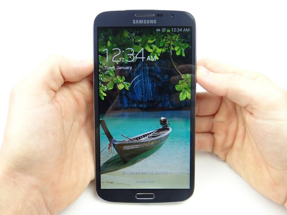
Power up and test device.
-