-
-
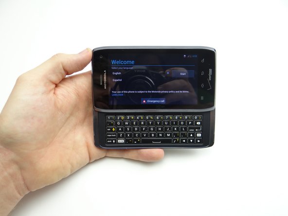
Power down device.
-
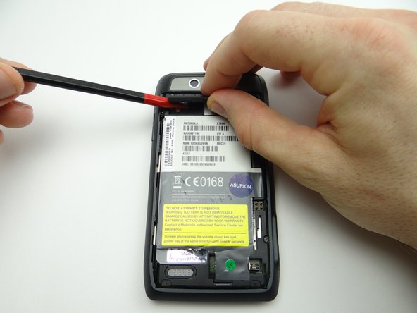
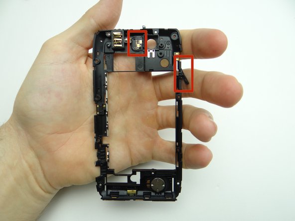
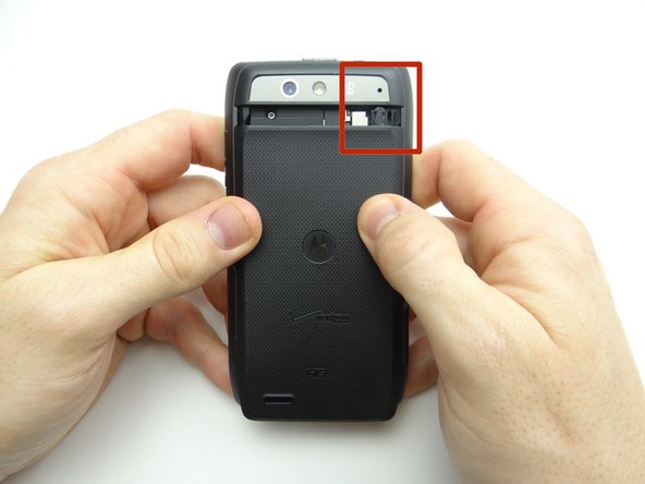
There's a pressure tab holding the battery cover in place. In the next step, you'll depress the tab by pushing a small paperclip into the opening in the red square.
-
Motorola makes a tool to depress the tab holding the battery cover, but a paper clip works fine in a pinch.
-
-
-
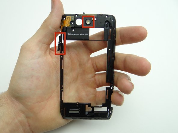
Push a small paper clip into the opening on the rear camera cover with one hand, while sliding the battery cover down with the other hand. Keep pressure on the paper clip until the battery cover moves with minimal effort.
-
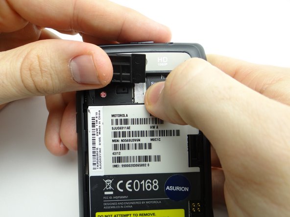
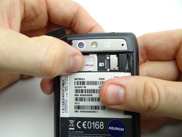
Continue sliding battery cover down until the tab (red square) is free.
-
Place battery cover in ZONE I.
-
-
-
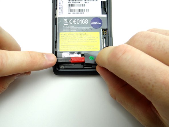
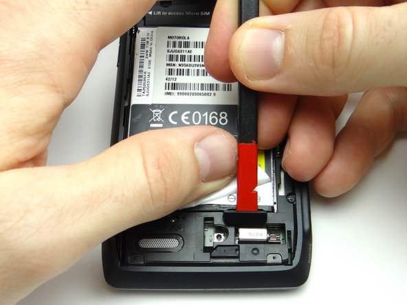
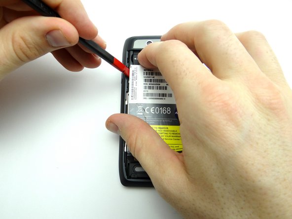
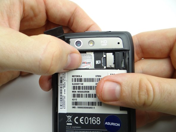
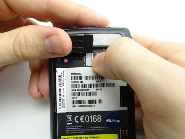
Use the flat edge of the spudger to lift the tab on the lower-right corner of the IMEI sticker. Grab the tab with your fingers and hold it back.
-
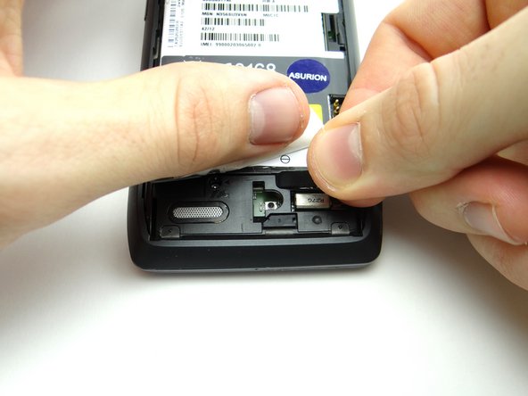
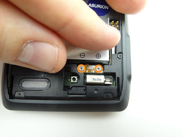
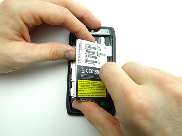
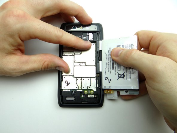
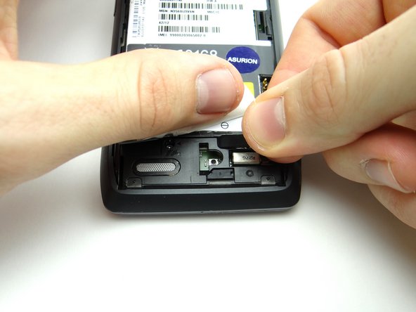
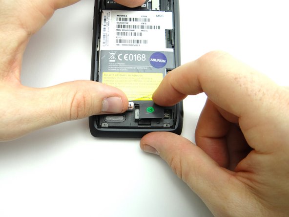
Pictures 2 & 3: Use the flat end of the spudger to pry up the cover just below the '- +' signs on the battery. Finish removing cover with your fingers and place in SLOT 1.
-
-
-
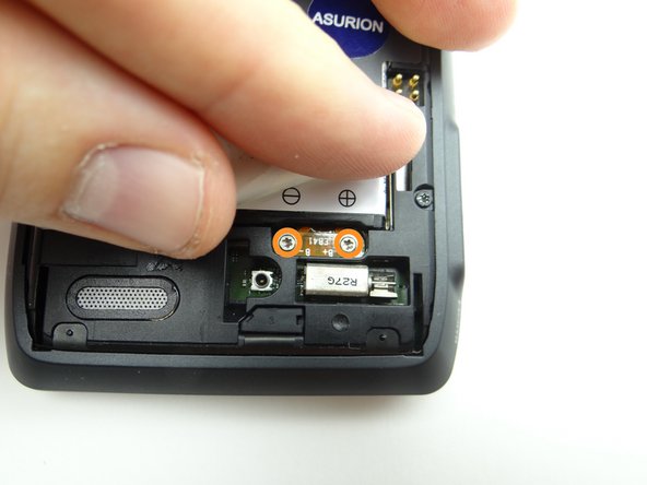
Picture 1: Remove two 3.3 mm T5 Torx screws with washers. Place screws in SLOT 1 (with the cover). Make sure the washers stay with the screws.
-
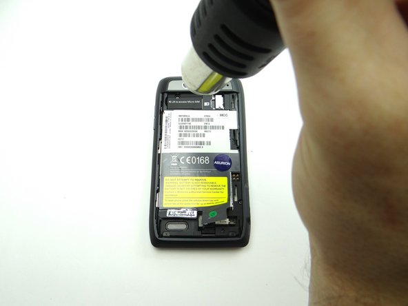
The battery is held in place with strong adhesive:
-
Apply low-level heat (100° Celsius or less) to the left side of the battery for 30 seconds or less to loosen the adhesive.
-
Use the flat end of the spudger to pry up the upper-left corner of the battery.
-
-
-
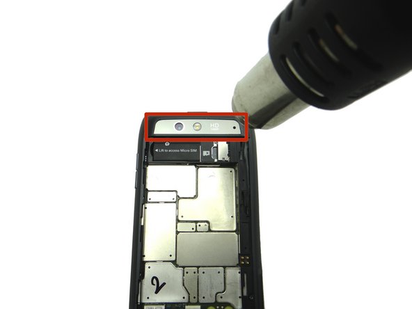
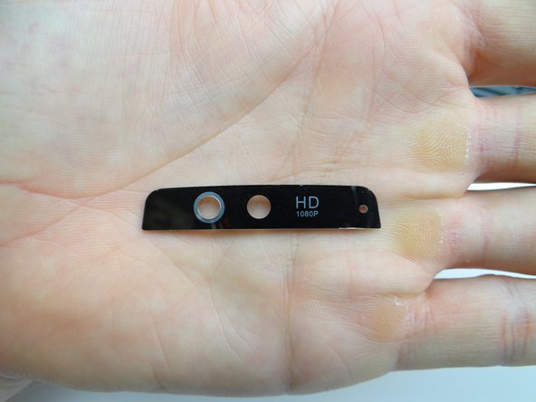
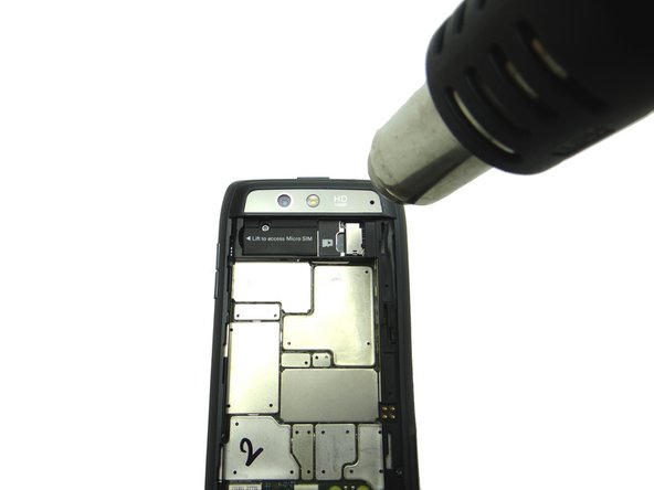
Picture 1: Heat the rear camera trim for 30 seconds to loosen the mild adhesive holding it in place.
-
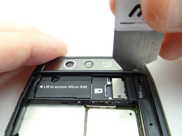
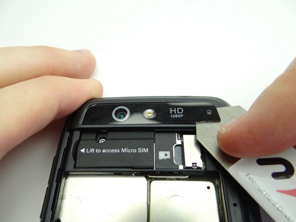
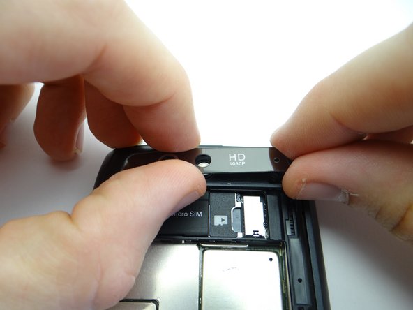
Pictures 2 & 3: Wedge the iSesamo between the camera trim and rear frame in the lower-left corner. Carefully work your way under the right side of the trim.
-
-
-
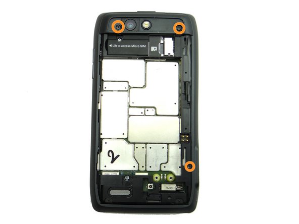
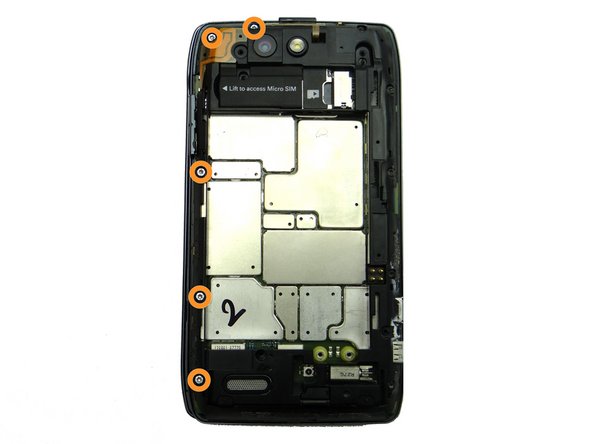
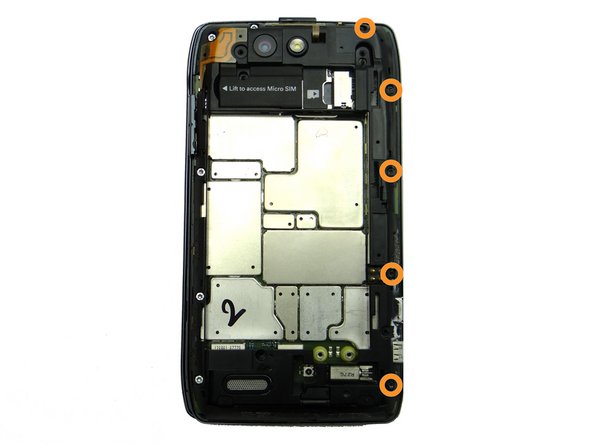
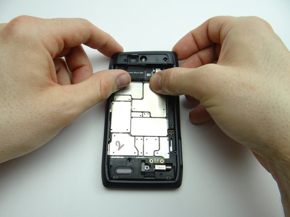
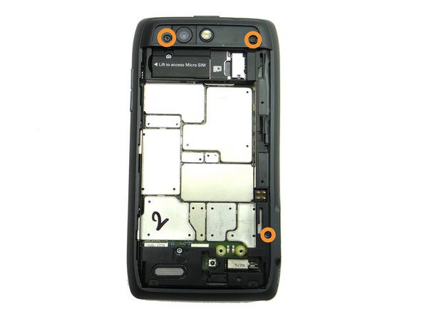
Picture 1: Remove three 4.2 mm black T5 Torx screws. Place in SLOT 2.
-
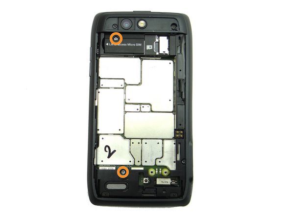
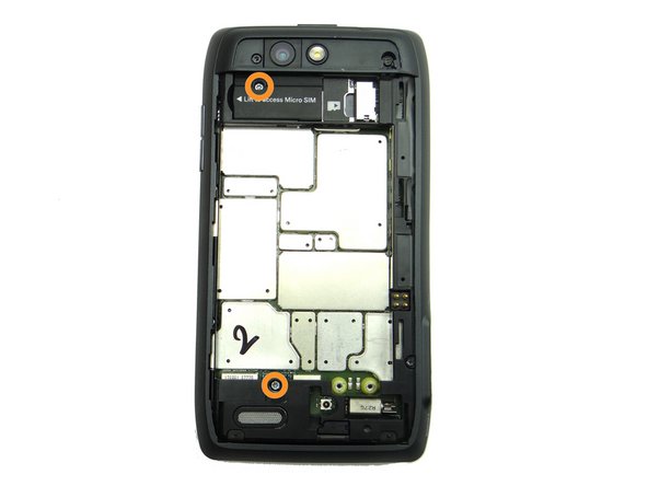
Picture 2: Remove two 4.3 mm silver T5 screws. Place in SLOT 3.
-
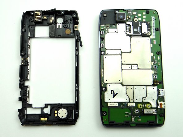
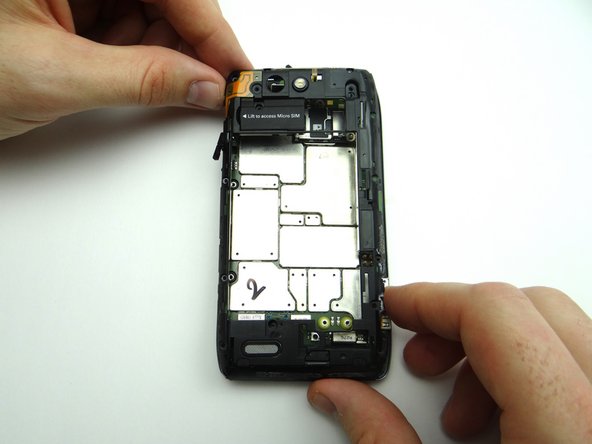
The rear frame is held in place with mild adhesive:
-
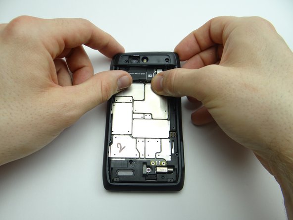
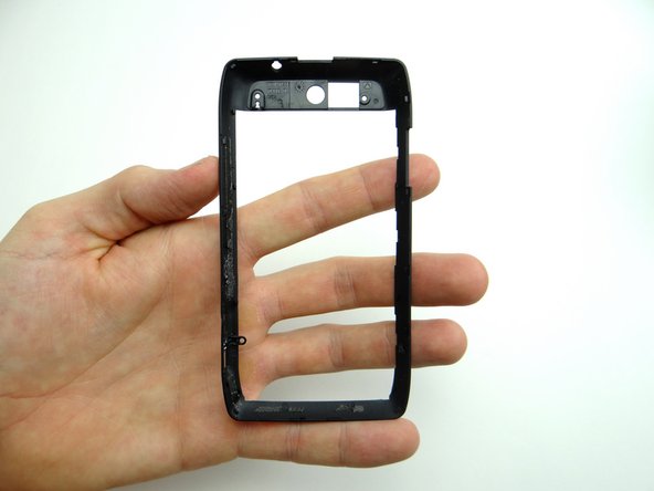
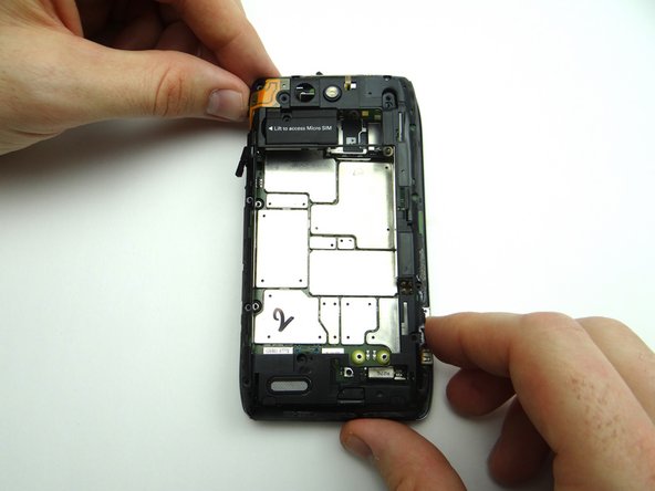
Picture 3: Peel up upper-right corner of rear frame.
-
-
-
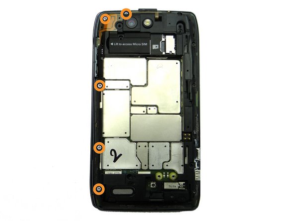
Picture 1: From the left side of the phone, remove five 4.1 mm silver T5 Torx screws. Place in SLOT 4.
-
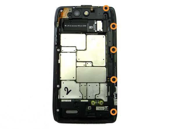
Picture 2: From the right side of the phone, remove five 4.3 mm black T5 Torx screws. Place in SLOT 5.
-
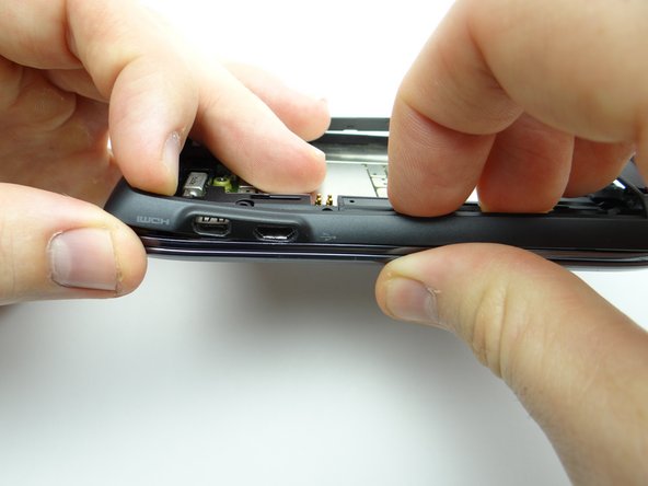
Picture 3: Lift mid-frame away from phone.
-
-
-
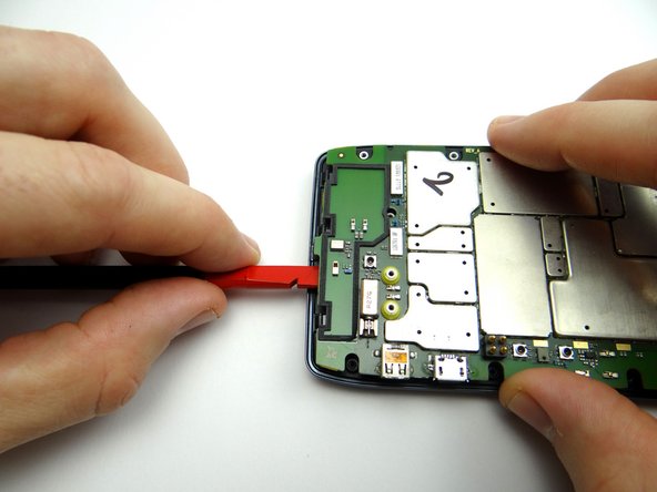
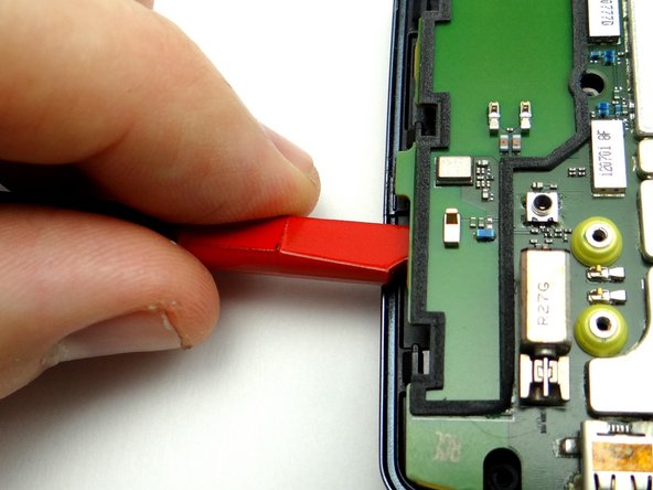
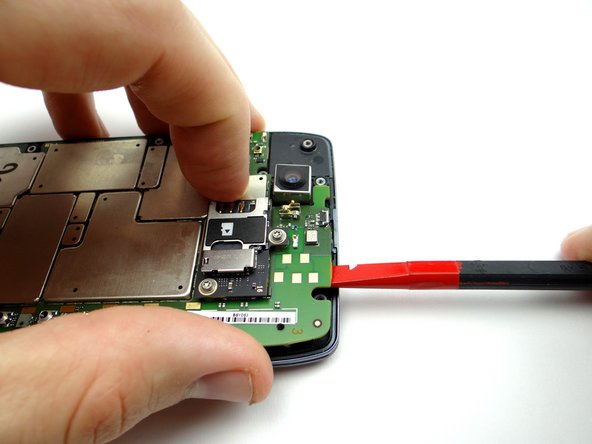
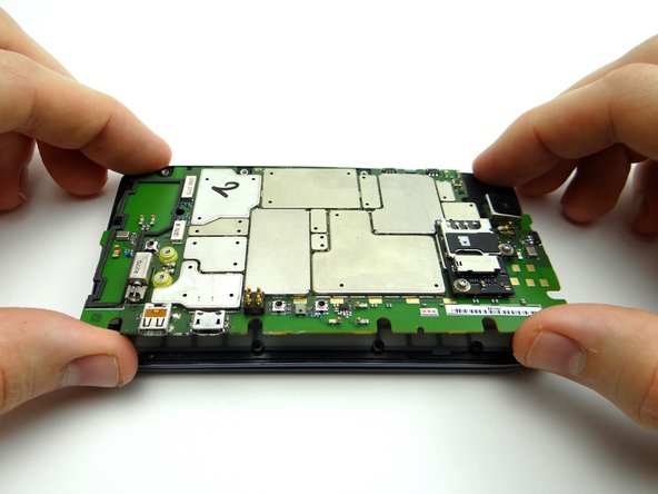
Mild adhesive helps hold the logic board in place:
-
Use the flat end of the spudger to pry up the bottom of the logic board slightly.
-
Wedge under the logic board until you reach the notch in the spudger (as shown in Picture 3). Lift slightly to free the bottom of the board from the adhesive holding it down.
-
-
-
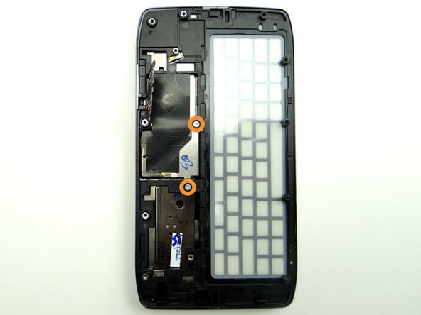
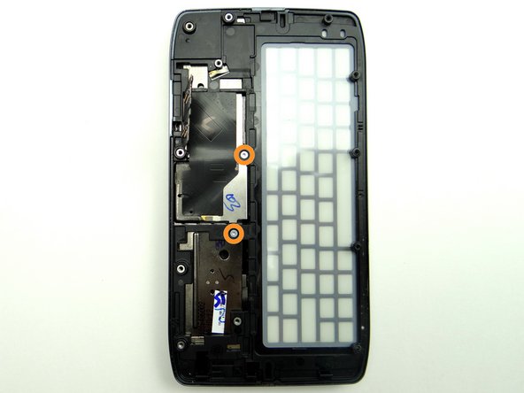
Remove two silver 1.7 mm T3 Torx screws. Place in SLOT 6.
-
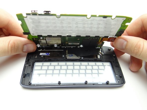
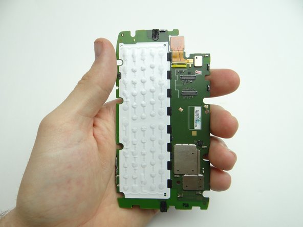
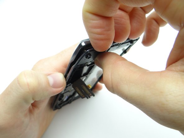
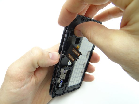
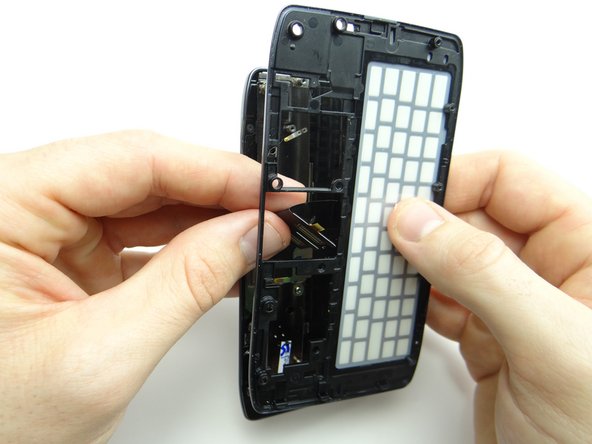
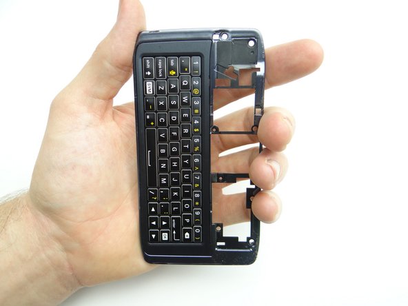
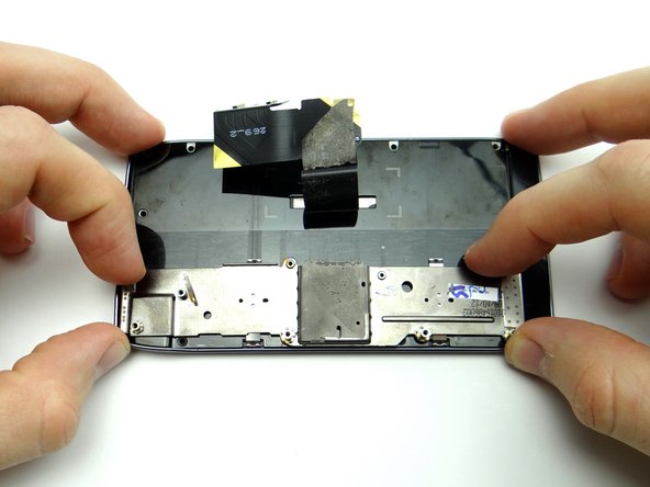
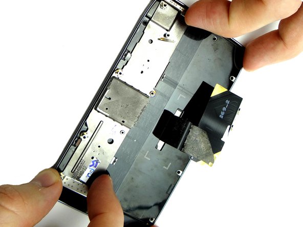
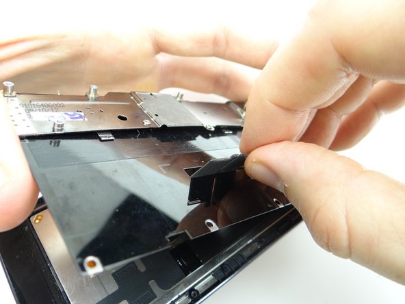
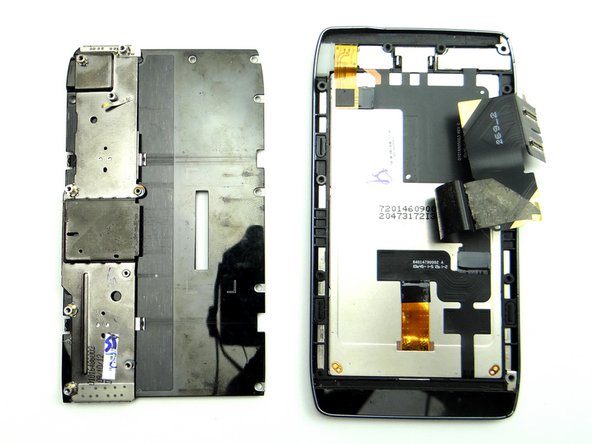
Separate the keyboard assembly from the front panel, starting in the upper-left corner.
-
-
-
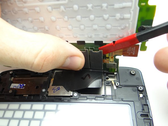
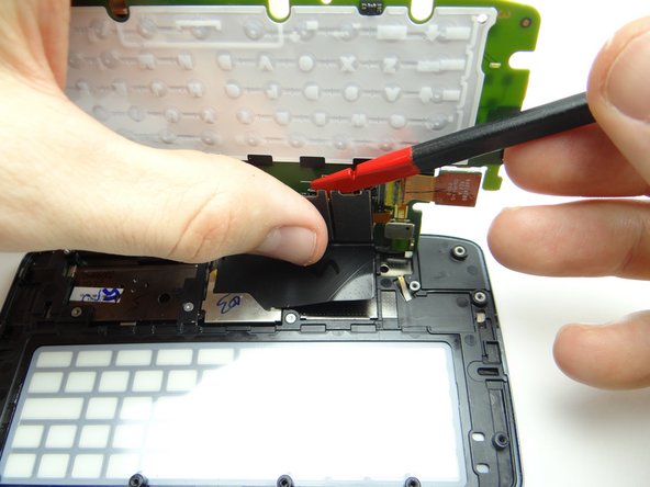
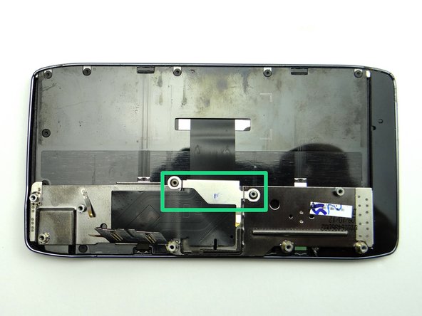
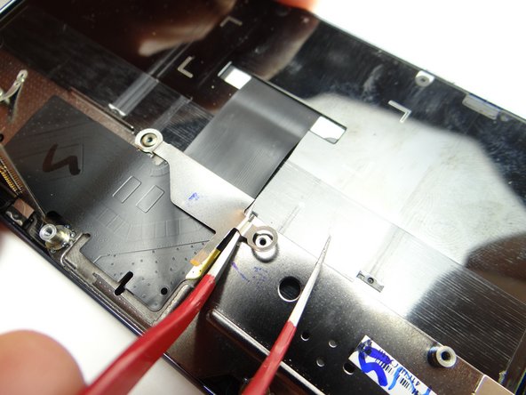
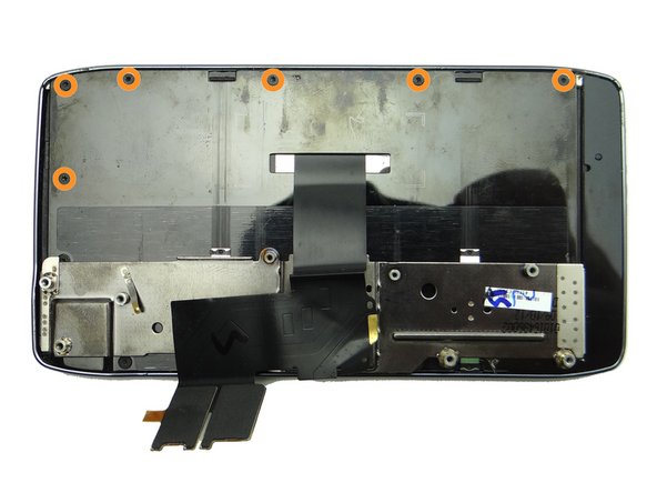
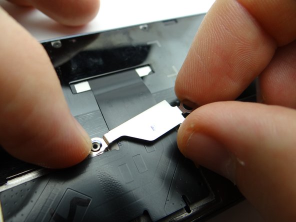
Use curved-tip tweezers to remove the bracket pictured:
-
Use one prong of the tweezers to lift the bracket away from the phone.
-
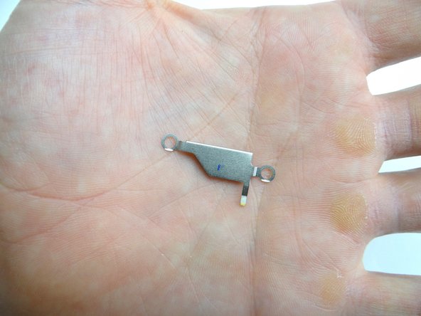
Place bracket in COMPARTMENT B.
-
-
-
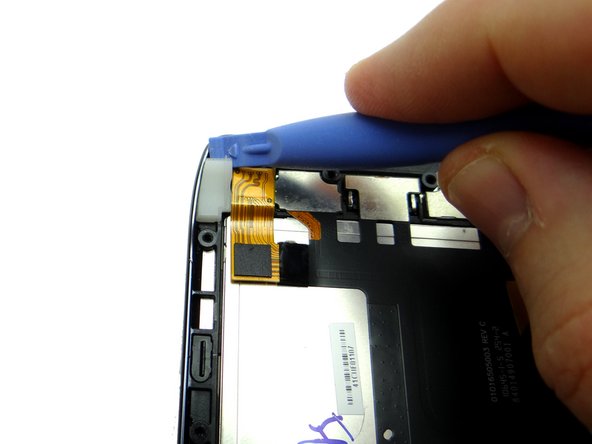
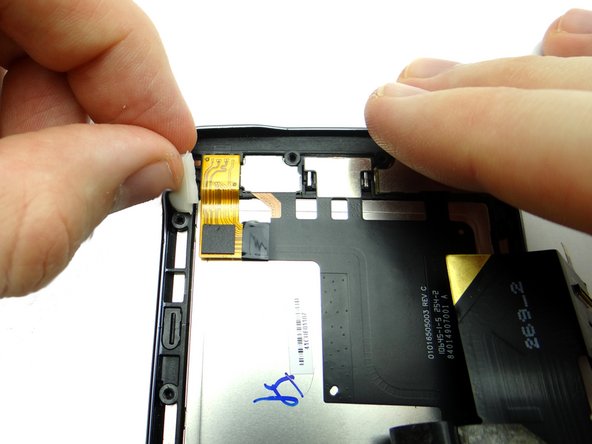
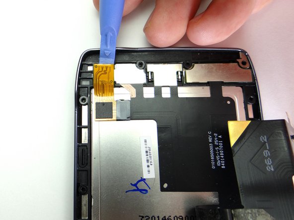
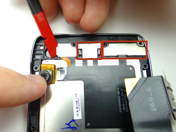
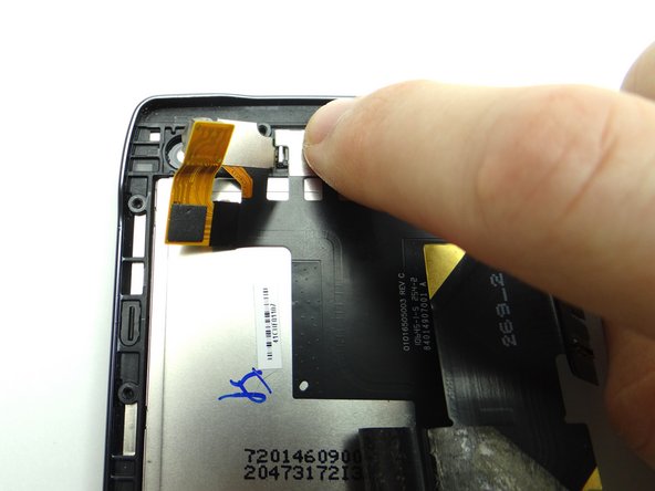
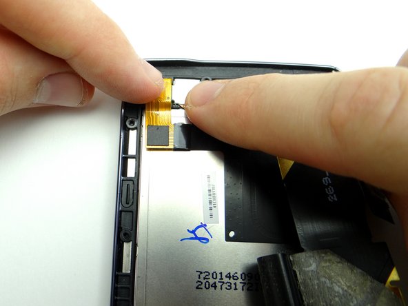
Lift the edge of the rubber gasket in the upper-left corner of the display assembly.
-
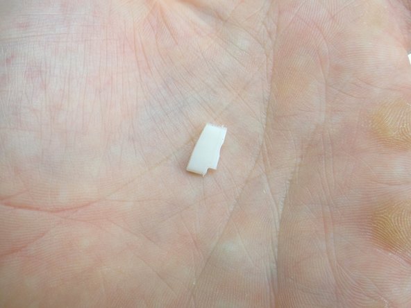
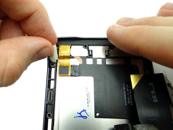
Remove the rubber gasket with your fingers and place it in COMPARTMENT D.
-
-
-
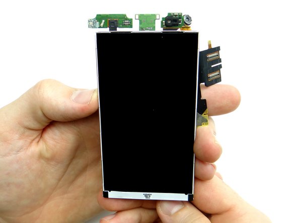
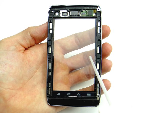
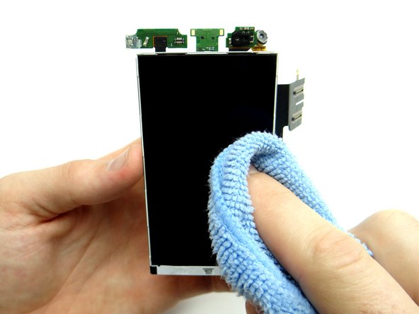
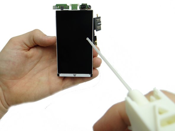
If you're reusing the LCD, clean it with a chamois cloth and compressed air.
-
-
-
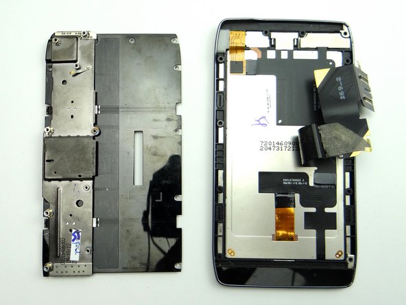
Attach metal plate to display assembly:
-
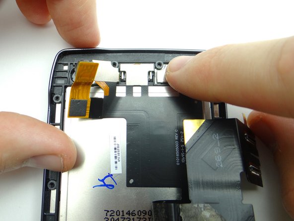
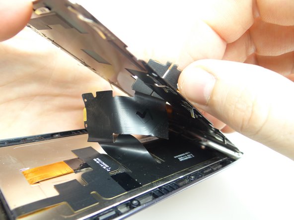
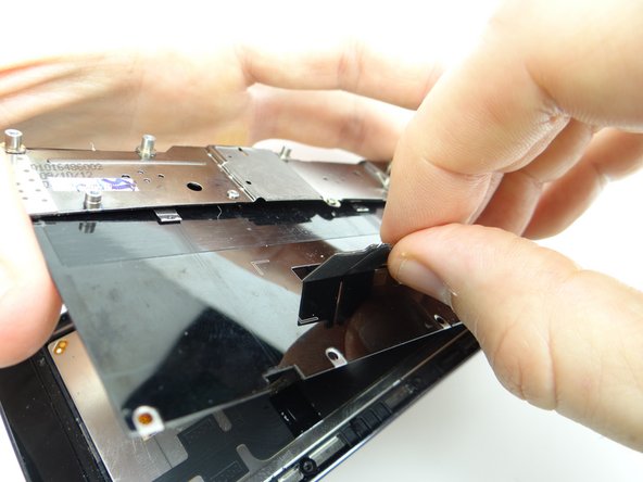
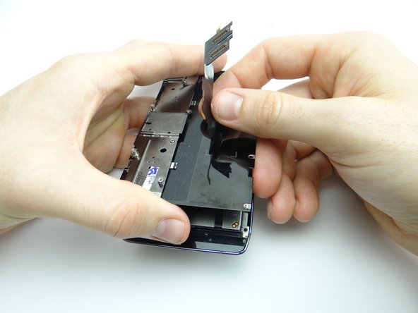
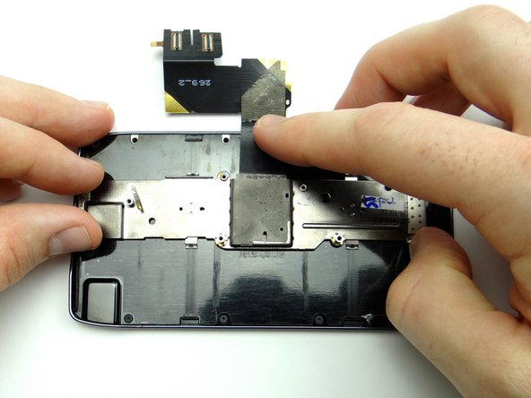
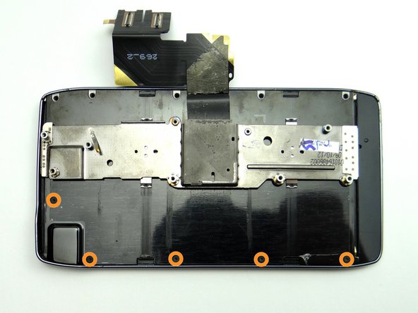
Feed display assembly cable through while seating metal plate.
-
-
-
Picture 1: Retrieve the keyboard:
-
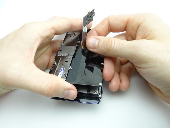
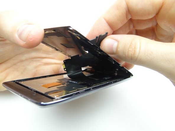
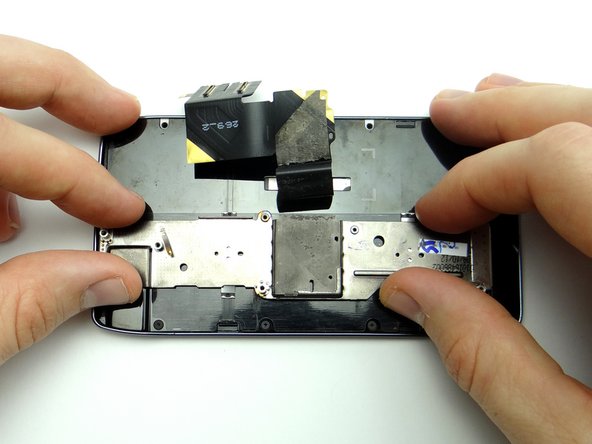
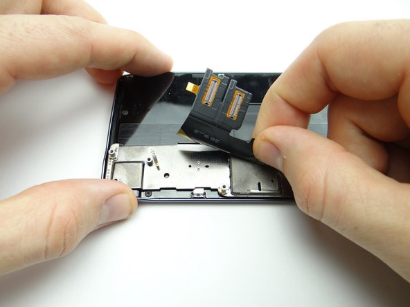
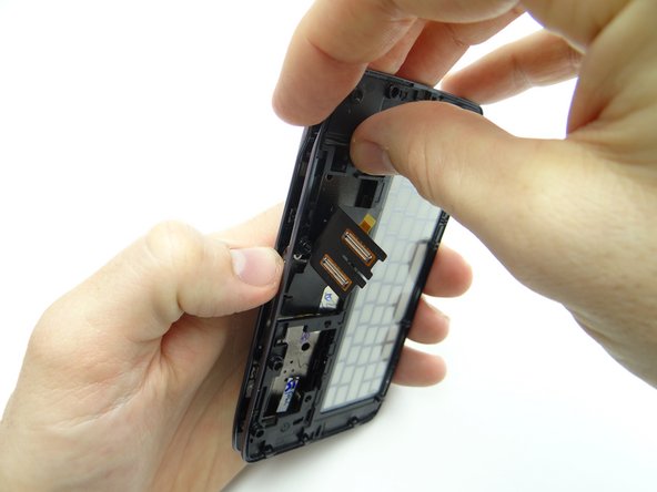
Pictures 2 & 3: Feed the display assembly cable through the opening in the keyboard assembly while pushing the two together.
-
-
-
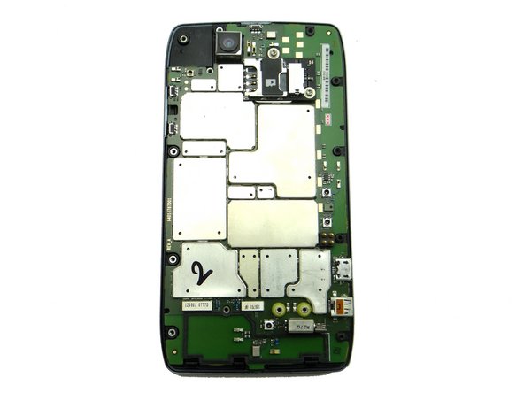
Retrieve logic board:
-
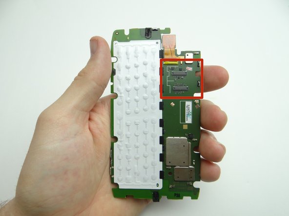
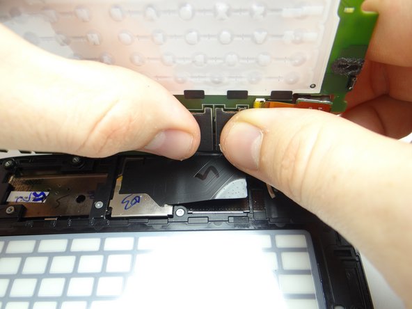
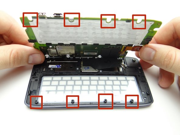
Picture 1: Line up the sockets on the logic board (red square) with the display cable connectors.
-
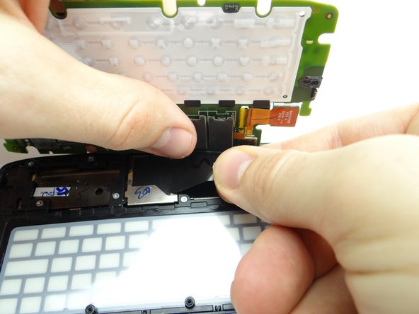
Pictures 2 & 3: Seat the display cable connectors.
-
-
-
Retrieve mid-frame, then:
-
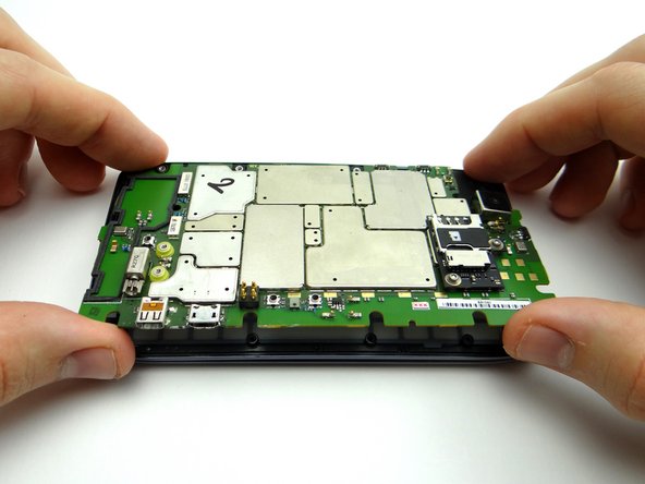
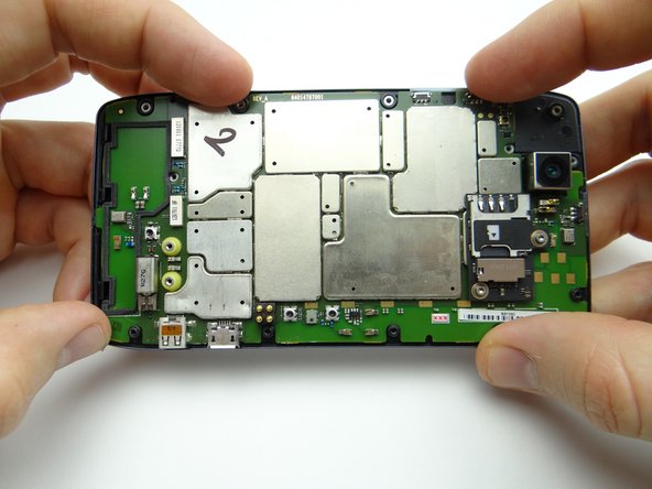
Seat the mid-frame on the phone while making sure the screw mounts line up with their corresponding openings on the mid-frame.
-
-
-
From ZONE II, seat rear frame:
-
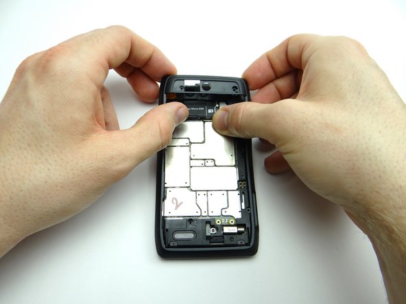
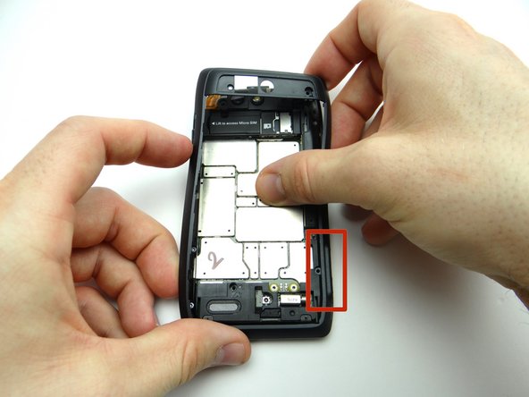
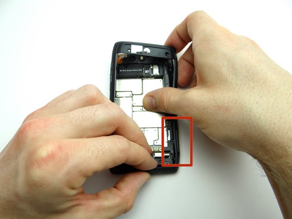
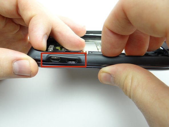
Seat the HDMI and charging ports first, then continue snapping rear frame into place.
-
-
-
Replace the rear camera trim from COMPARTMENT C:
-
Seat the trim, then apply low-level heat for 30 seconds to reinvigorate the adhesive.
-
Almost done!
Finish Line


