-
-
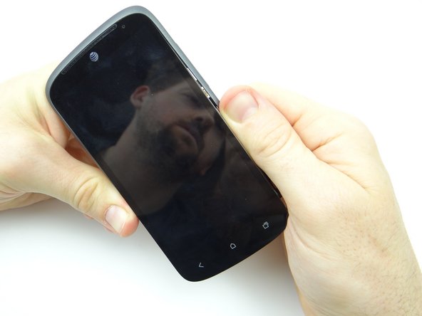
Power down the device.
-
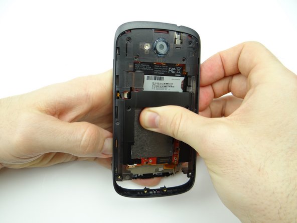
Remove the battery cover and place it in ZONE I.
-
-
-
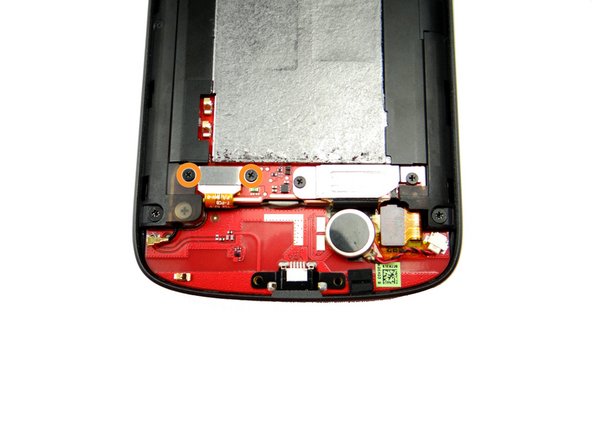
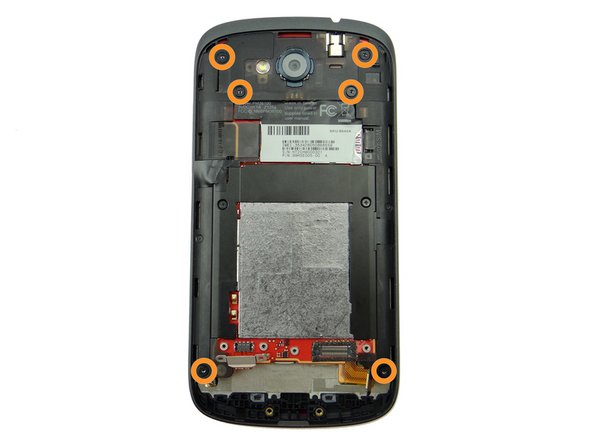
Remove two 3.6 mm T4 Torx screws. Place them in SLOT 1.
-
Use the pointed end of the spudger to pry up the speaker assembly. Remove it with your fingers and place it in ZONE I (below battery cover).
-
-
-
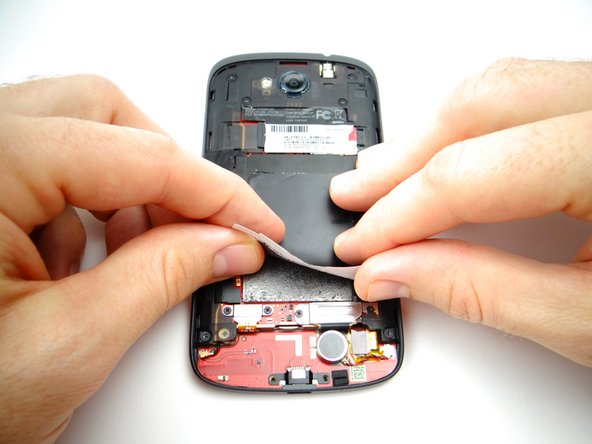
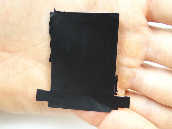
Peel up the tape covering the logic board.
-
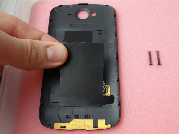
Place it on the inside of the battery cover in ZONE I, sticky side down.
-
-
-
Remove two 1.7 mm #00 Phillips screws from the battery connector. Place in SLOT 2.
-
Use flat end of spudger to disconnect the battery.
-
-
-
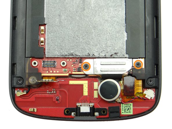
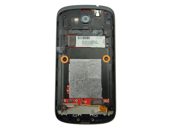
Picture 1: Remove two 1.8 mm #00 Phillips screws. Place in SLOT 3.
-
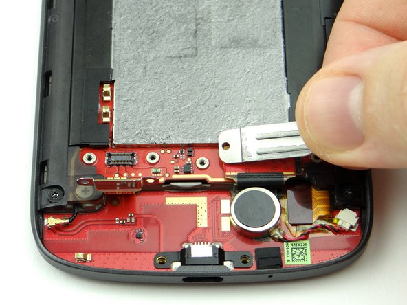
Picture 2: Remove the shield held down by the screws and place it in SLOT 3 (with the screws).
-
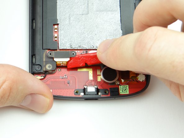
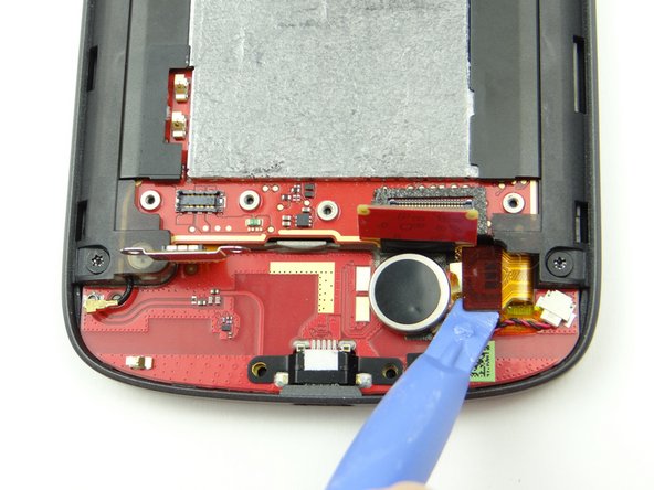
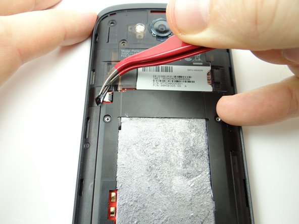
Use blue pry tool to disconnect charging port daughter board cable.
-
-
-
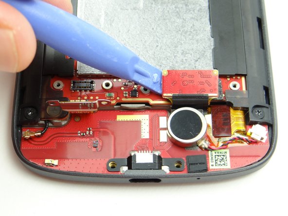
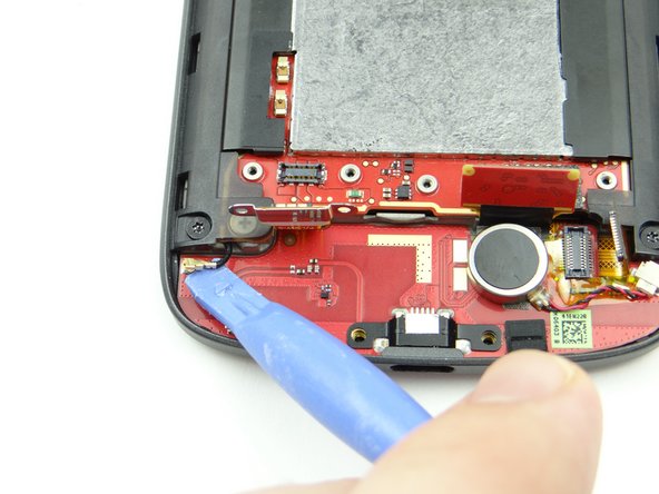
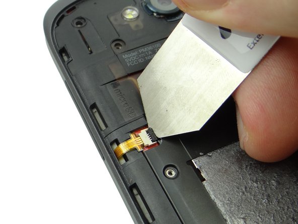
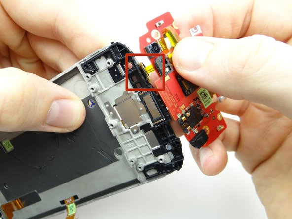
Picture 1: Use the blue pry tool to disconnect soft keys/digitizer cable.
-
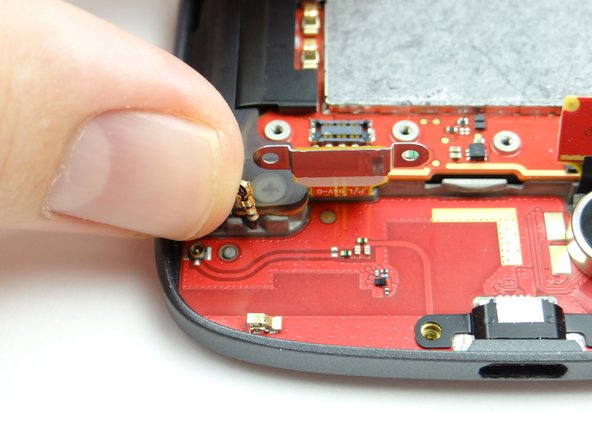
Pictures 2 & 3: Disconnect antenna then gently bend straight up (so it's out of the way when you remove the charging port board).
-
-
-
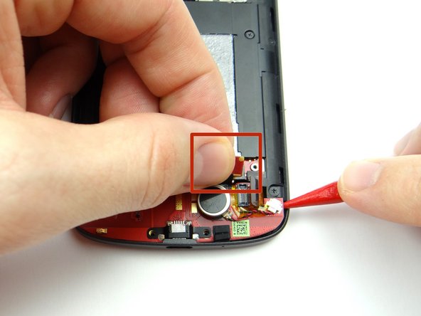
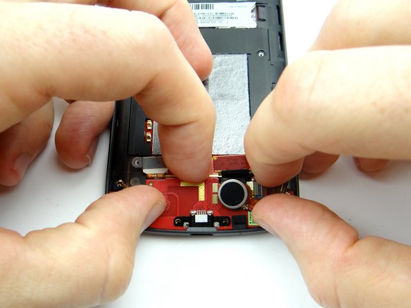
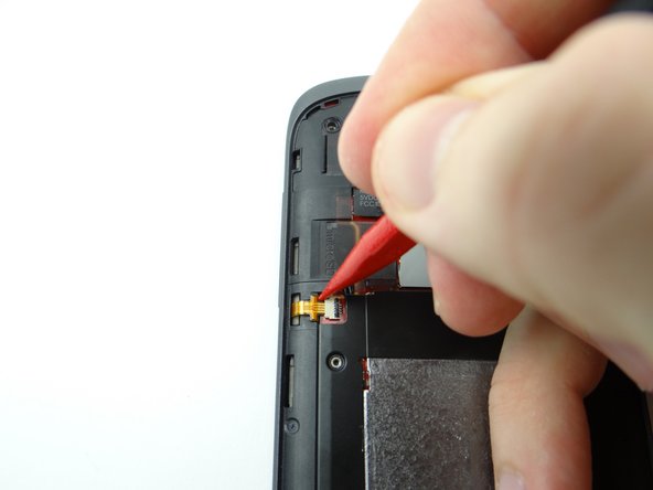
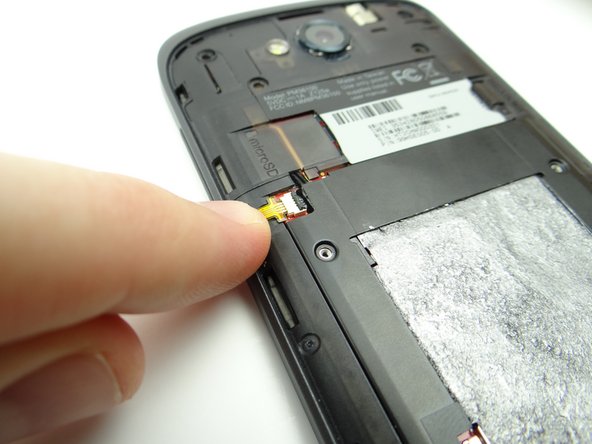
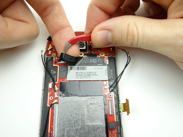
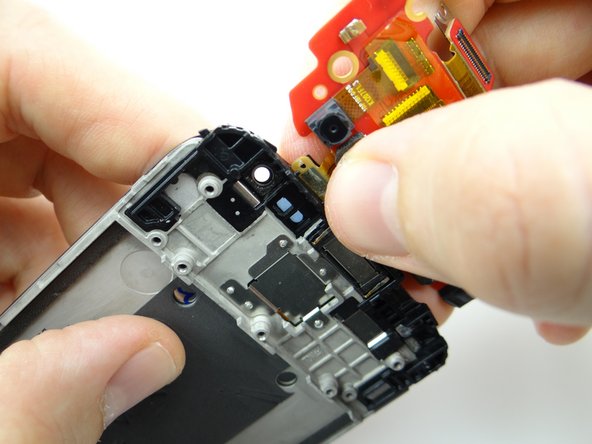
Gently pull up on the charging port board cable (red square) while using the pointed tip of the spudger to wedge under the board and lift.
-
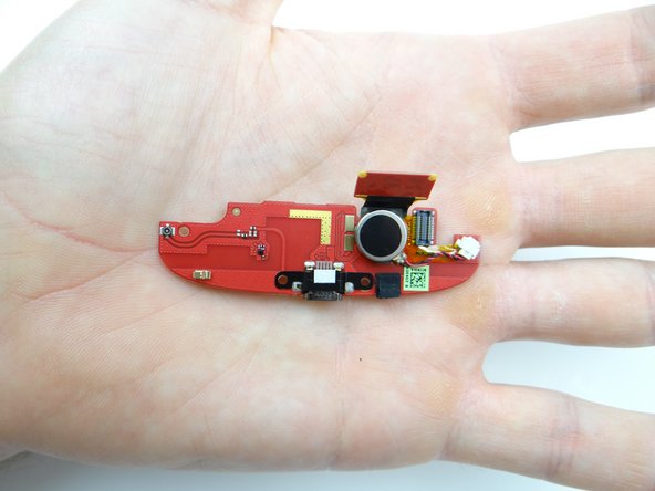
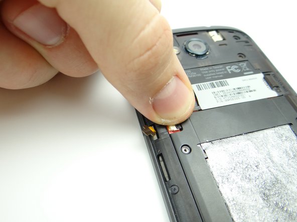
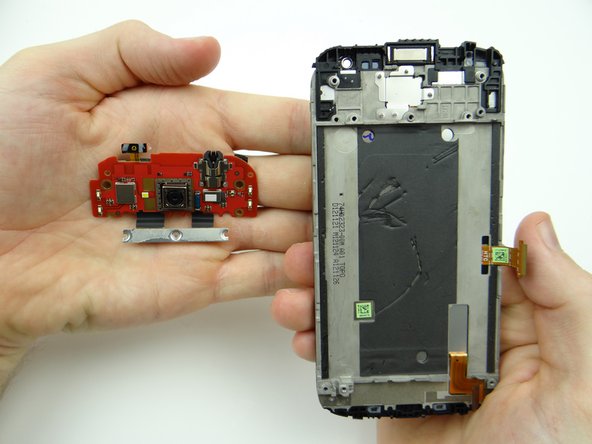
Use your fingers to finish removing the board.
-
Place charging port daughter board in ZONE II.
-
-
-
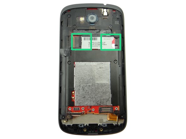
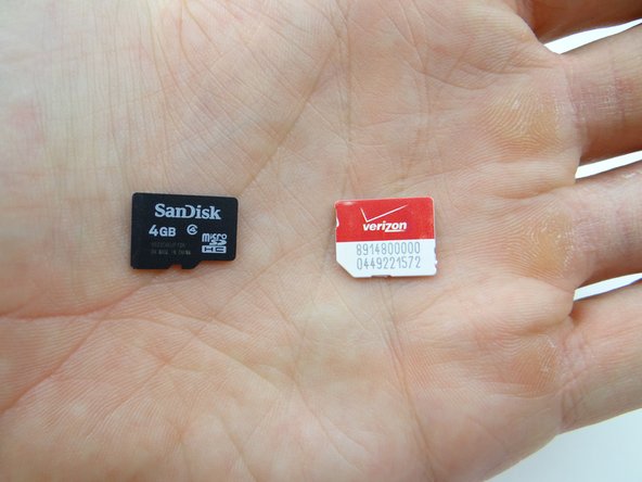
Remove SD and SIM cards. Place in COMPARTMENT A.
-
-
-
Picture 1: Remove six 3.6 mm T4 Torx screws. Place in SLOT 1 (with two bottom screws).
-
Picture 2: Remove two 1.7 mm #00 Phillips screws. Place in SLOT 2 (with battery connector screws).
-
-
-
Use curved tip tweezers to peel up electrical tape covering volume cable connector. Adhere tape to wall of COMPARTMENT B.
-
The bar on the ZIF connector is small and fragile. Take care when performing this step:
-
Use the tip of the iSesamo to open the ZIF connector.
-
-
-
Pictures 1 & 2: Use the pointed tip of the spudger to push the cable away from the socket slightly. Use your finger to finish pulling the cable free.
-
Picture 3: Close the ZIF connector to ensure it doesn't get disturbed/broken as you continue to disassemble the phone.
-
-
-
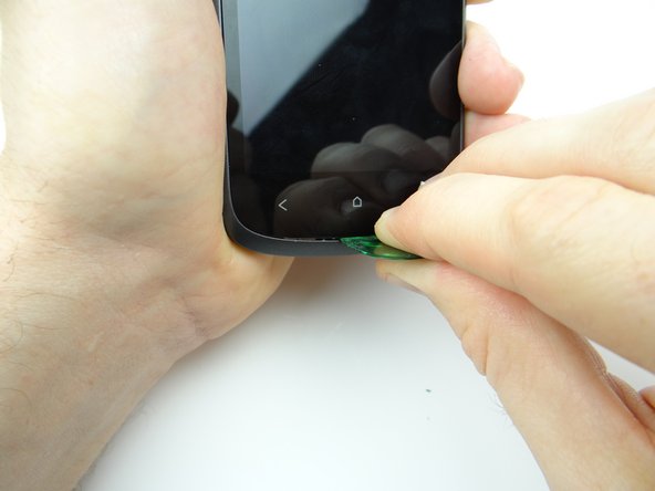
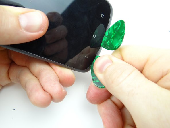
Picture 1: Use a guitar pick to wedge directly under the home soft key.
-
Picture 2: Wedge a second guitar pick directly under the escape soft key.
-
Picture 3: Use your fingers to continue separating the mid-body from the front panel, starting in the lower-left corner.
-
-
-
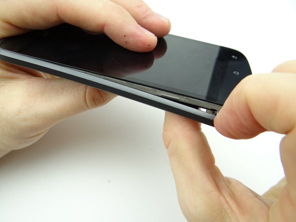
Picture 1: Continue separating along the right side.
-
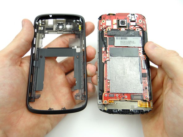
Picture 2: Turn the phone over, then finish removing the mid-body.
-
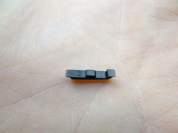
Picture 3: The power button will fall out as you're removing the mid-body. Place it in COMPARTMENT B.
-
-
-
Place the mid-body or front panel in ZONE II depending on the repair needed.
-
-
-
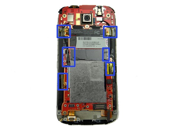
Picture 1: Remove the Kapton tape and electrical tape outlined in the blue rectangles.
-
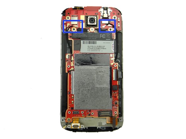
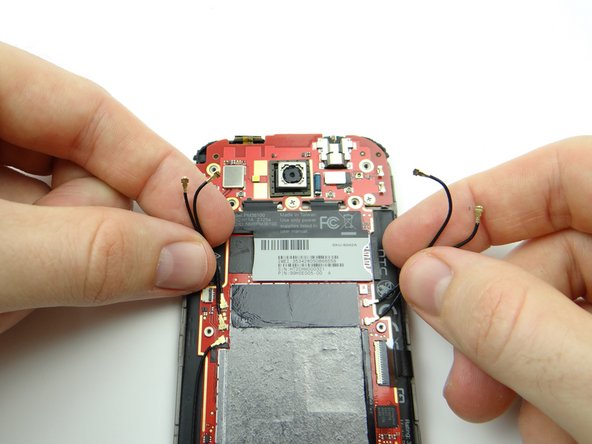
Picture 2: Use the blue pry tool to disconnect the four antenna cables from the daughter board.
-
Picture 3: Gently bend the four cables away from the upper logic board.
-
-
-
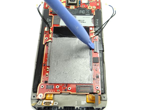
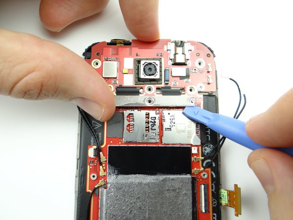
Picture 1: Use the blue pry tool to open the LCD cable ZIF connector.
-
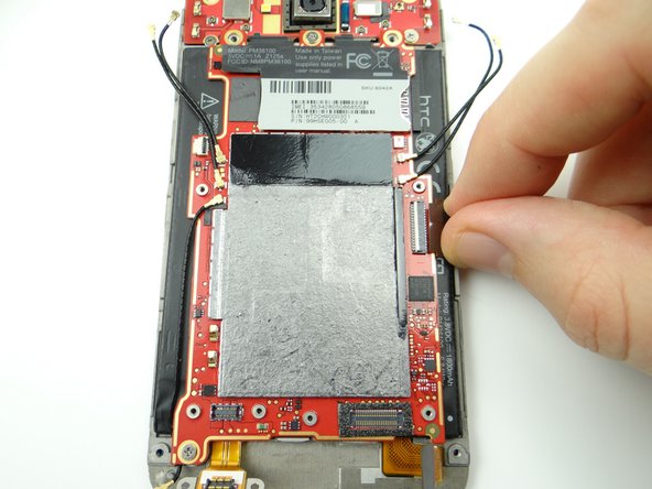
Picture 2: Use your fingers to pull the LCD cable free.
-
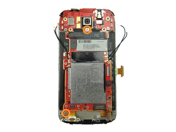
Picture 3: Remove two 2.6 mm Phillips #00 screws from the logic board. Place them in SLOT 4.
-
-
-
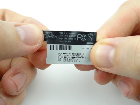
Picture 1: Take care not to touch the logic board as you pinch the upper-left corner of the IMEI sticker with curved tip tweezers. Peel it up until you can wedge your finger under the sticker.
-
Picture 2: Continue peeling up the sticker with your fingers. Place the IMEI sticker against the wall of compartment D.
-
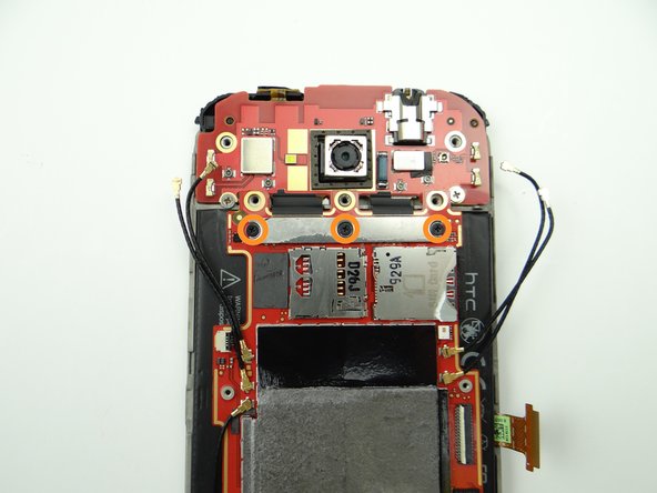
Picture 3: Remove three 1.6 mm #00 Phillips screws holding upper logic board to main logic board. Place in SLOT 5.
-
-
-
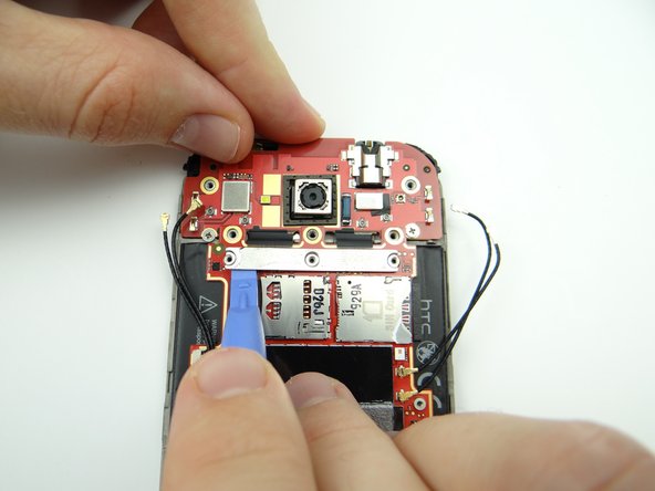
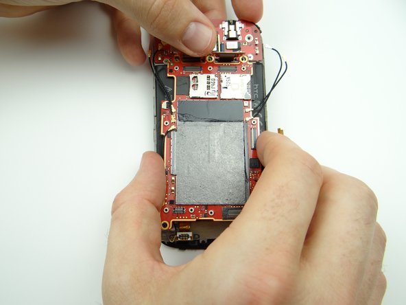
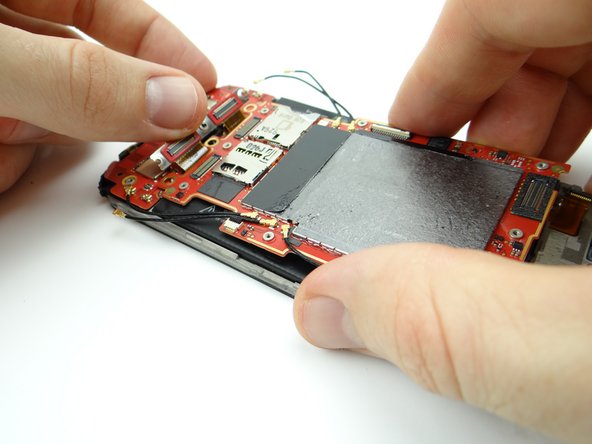
Lift the left and right sides of the silver connector bar.
-
-
-
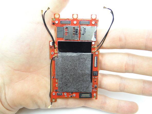
Lift the connector bar up and out of the way as you carefully remove the logic board from the front panel.
-
Place logic board in ZONE III.
-
-
-
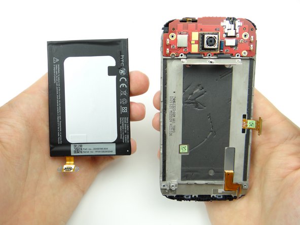
Strong adhesive runs the length of the battery on either side, holding it to the front panel. Additionally, there's a circuit board at the bottom of the battery. Take extra care to avoid bending the circuit board:
-
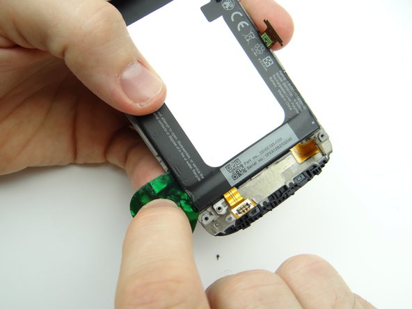
Picture 1: Use a guitar pick to push under the lower-left corner of the battery to cut through the adhesive.
-
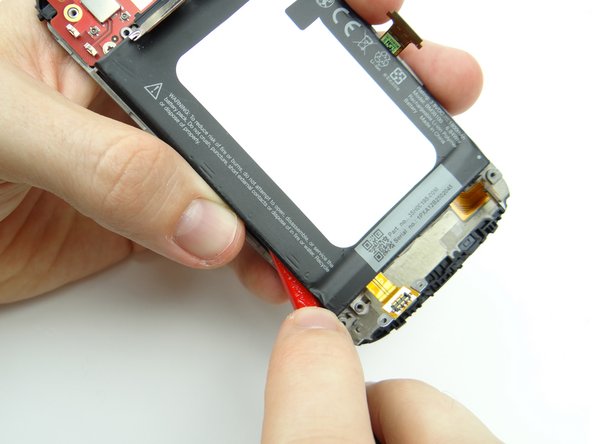
Picture 2: Wedge the flat end of the spudger where you inserted the guitar pick. Work your way up the left side to separate the adhesive
-
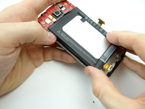
Picture 3: Use your thumbs to lift the left side of the battery slightly.
-
-
-
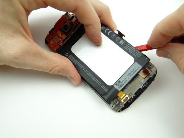
Use the spudger to work your way up the right side of the battery until it's free.
-
Place the battery in ZONE IV, adhesive side up.
-
-
-
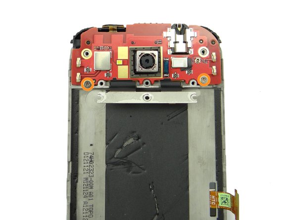
Picture 1: Remove two 2.7 mm #00 Phillips screws from upper logic board. Place in SLOT 6.
-
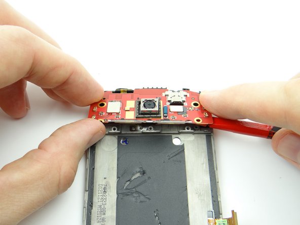
Don't try to remove the daughter board completely in this step. The power button is still adhered to the front panel:
-
Pictures 2 & 3: Wedge the flat end of the spudger under the lower-right corner of the daughter board. Lift the daughter board with your fingers.
-
-
-
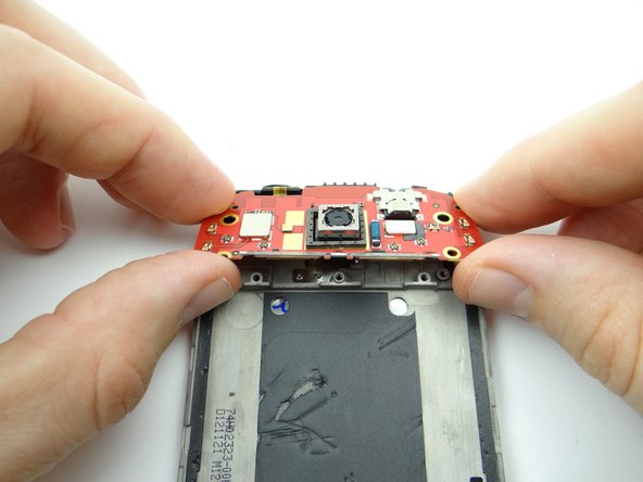
Pictures 1 & 2: While holding the front panel in your left hand, use your right hand to rotate the upper board away from the front panel to expose the power button cable (red square). Carefully peel up the power button cable with your fingers.
-
Picture 3: Place the upper logic board in ZONE V.
-