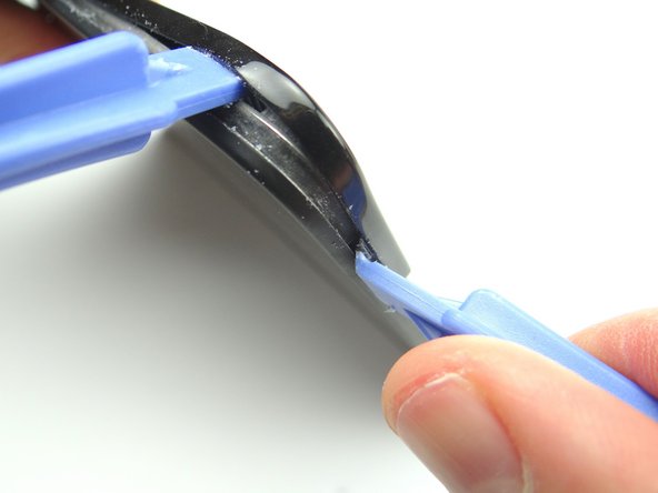
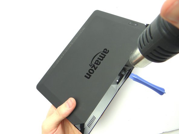
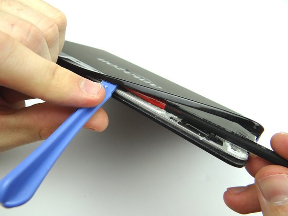
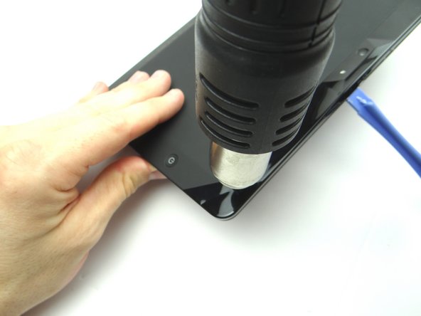
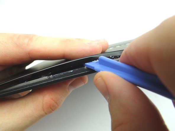
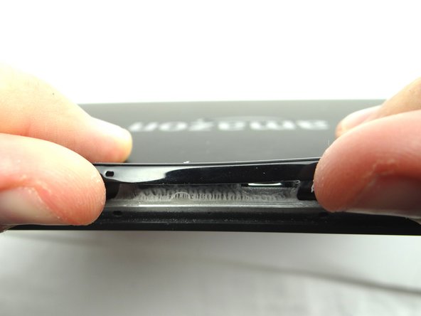
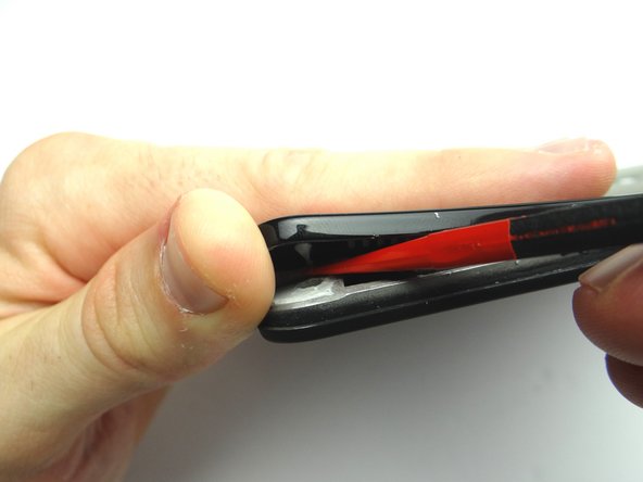
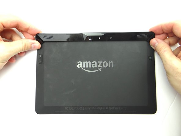
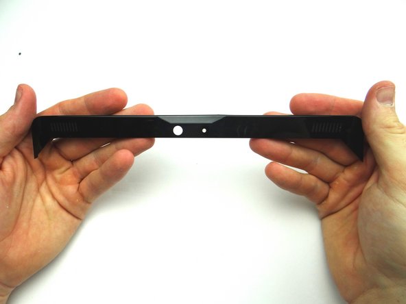
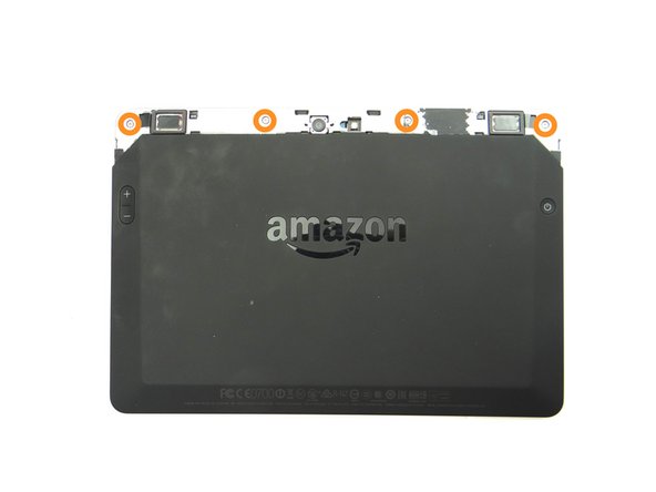
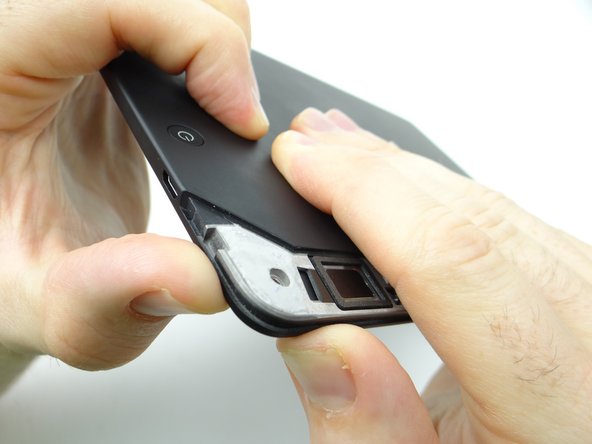
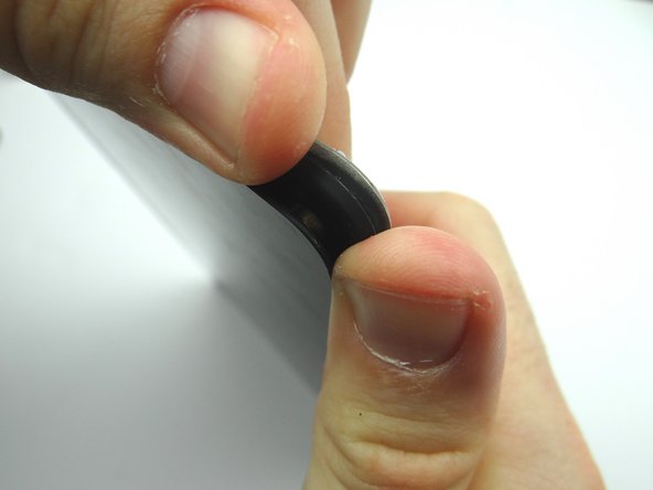
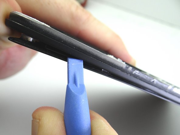
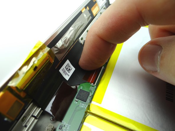
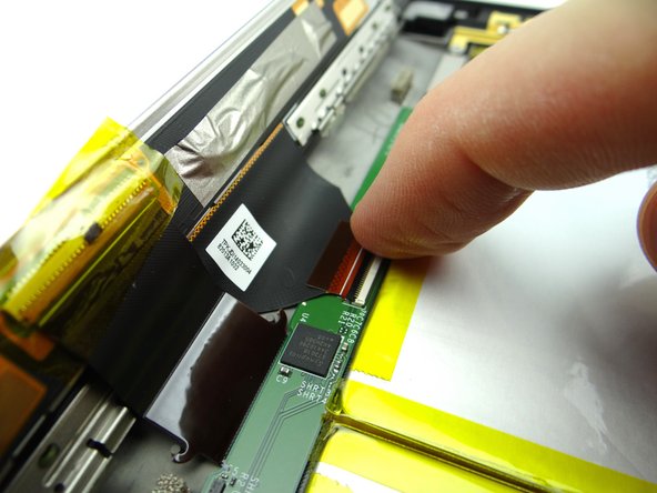
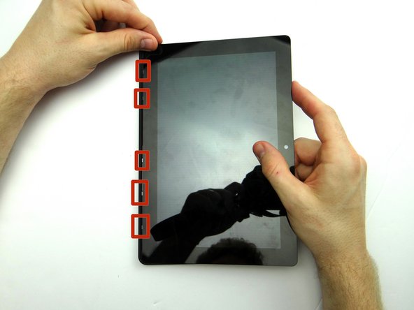
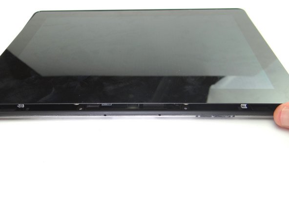
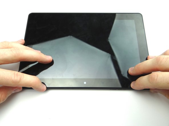
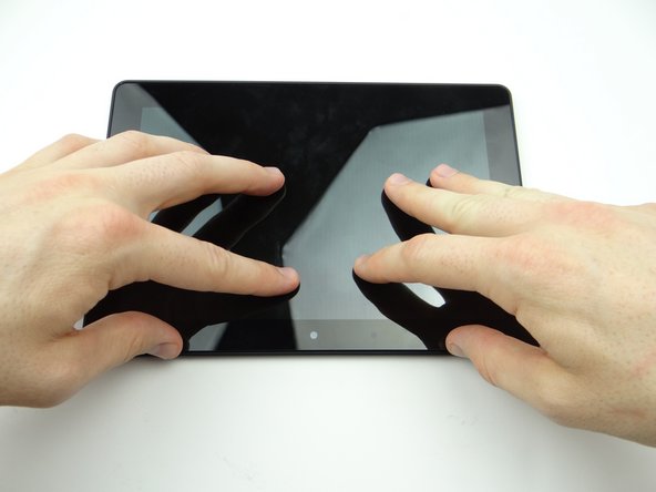
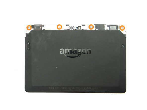
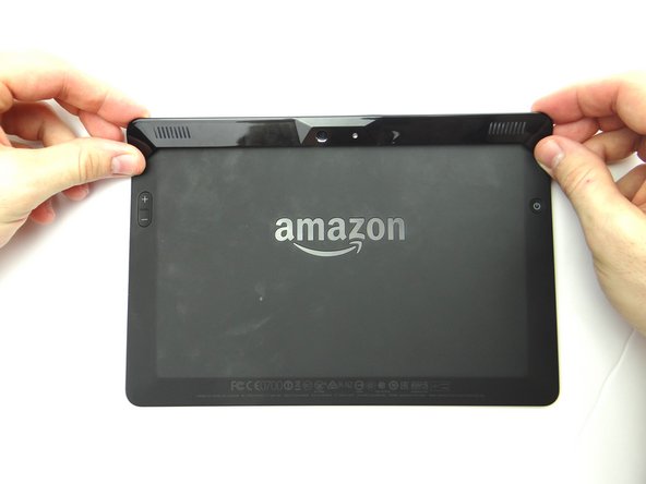
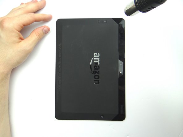
1. Power down the device. You'll be removing the trim (red square) in the next few steps: Apply low level heat (100° Celcius) to the corner of the trim.
    • Power down the device.

    • You'll be removing the trim (red square) in the next few steps:

    • Apply low level heat (100° Celcius) to the corner of the trim.

  2. To begin removing the trim: insert blue pry tool face up between the rear camera and the corner. Insert a wide blue pry tool (just right of the first pry tool) and work towards the corner near the volume buttons.
    • To begin removing the trim: insert blue pry tool face up between the rear camera and the corner.

    • Insert a wide blue pry tool (just right of the first pry tool) and work towards the corner near the volume buttons.

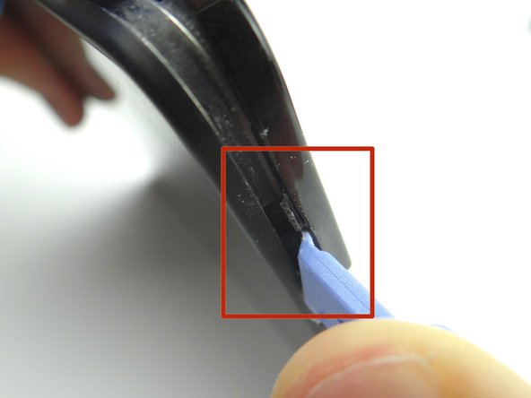
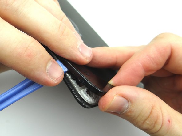
  3. Pictures 1 & 2: Use a blue pry tool (face up) to pry up the bottom of the trim near the volume rocker.  Gently pry up to release the tab (red square). Picture 3: Using your fingers, gently pry up the corner of the rear trim. Picture 3: Using your fingers, gently pry up the corner of the rear trim.
    • Pictures 1 & 2: Use a blue pry tool (face up) to pry up the bottom of the trim near the volume rocker. Gently pry up to release the tab (red square).

    • Picture 3: Using your fingers, gently pry up the corner of the rear trim.

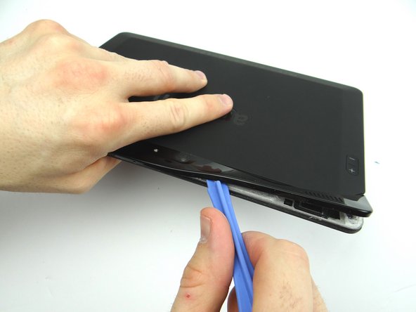
  4. Picture 1: Use the wide blue pry tool to work your way towards the camera. Picture 2: Apply heat as needed. Picture 3: Use the flat end of the spudger to cut through adhesive.
    • Picture 1: Use the wide blue pry tool to work your way towards the camera.

    • Picture 2: Apply heat as needed.

    • Picture 3: Use the flat end of the spudger to cut through adhesive.

  5. Apply low level heat (100° Celcius) from the center to the power button. Work your way towards the corner.
    • Apply low level heat (100° Celcius) from the center to the power button.

    • Work your way towards the corner.

  6. Gently lift the trim using your fingers to expose the remaining adhesive. Use the flat end of the spudger to cut through it.
    • Gently lift the trim using your fingers to expose the remaining adhesive.

    • Use the flat end of the spudger to cut through it.

  7. Picture 1 & 2: Finish removing the rear trim with your fingers and place in ZONE I. Picture 3: Remove four pink 3.5 mm T5 Torx screws.  Place in SLOT 1. Picture 3: Remove four pink 3.5 mm T5 Torx screws.  Place in SLOT 1.
    • Picture 1 & 2: Finish removing the rear trim with your fingers and place in ZONE I.

    • Picture 3: Remove four pink 3.5 mm T5 Torx screws. Place in SLOT 1.

  8. Pictures 1 & 2: Using your thumbs, apply pressure to the rear case in the corner near the power button to begin separating the display assembly from the rear case. Picture 3: Insert a blue pry tool along the top edge between the display assembly and rear case. Picture 3: Insert a blue pry tool along the top edge between the display assembly and rear case.
    • Pictures 1 & 2: Using your thumbs, apply pressure to the rear case in the corner near the power button to begin separating the display assembly from the rear case.

    • Picture 3: Insert a blue pry tool along the top edge between the display assembly and rear case.

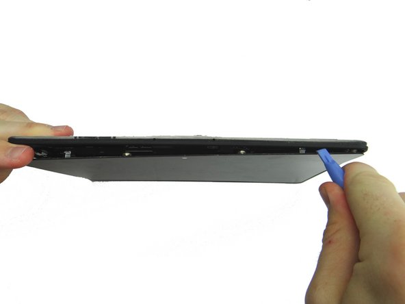
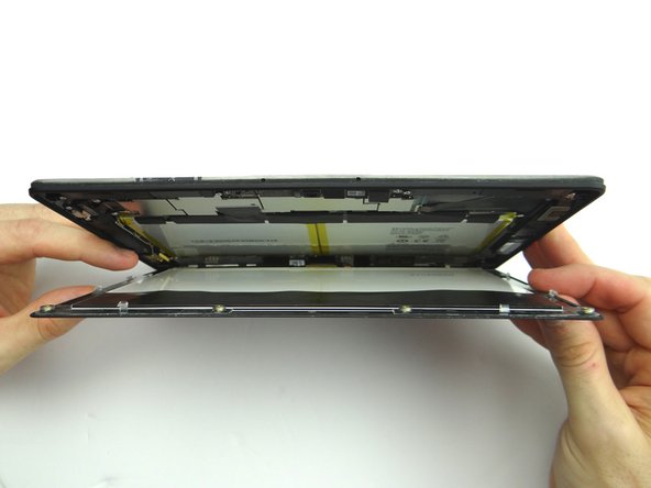
  9. Picture 1: Hold the corner open with your finger while using the blue pry tool to release the clips along the top of the display assembly. Picture 2: Open the screen like a book until all clips are released. Picture 3: Lay the rear case on the table with the display assembly open at a 90° angle, as shown.
    • Picture 1: Hold the corner open with your finger while using the blue pry tool to release the clips along the top of the display assembly.

    • Picture 2: Open the screen like a book until all clips are released.

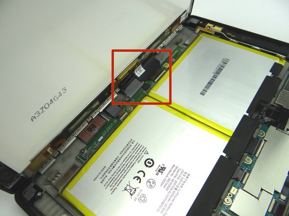
    • Picture 3: Lay the rear case on the table with the display assembly open at a 90° angle, as shown.

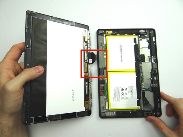
    • In the next couple step you'll release the display cables (red square):

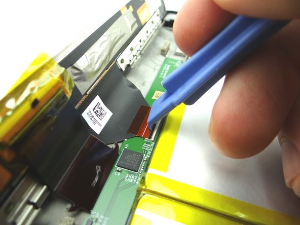
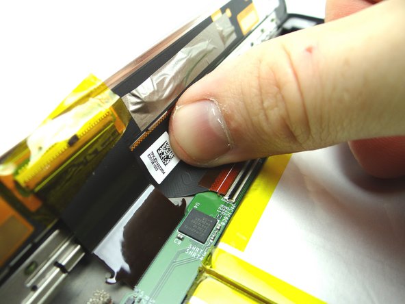
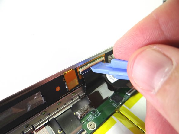
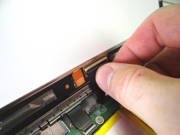
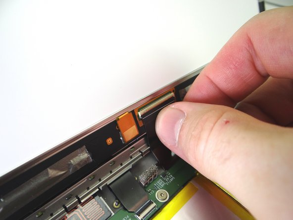
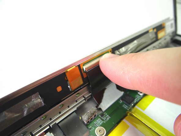
  10. Use the wide blue pry tool to move the ZIF connector black bar into open position as shown. Gently guide the display cable out of the ZIF connector.
    • Use the wide blue pry tool to move the ZIF connector black bar into open position as shown.

    • Gently guide the display cable out of the ZIF connector.

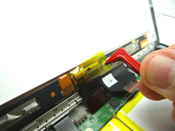
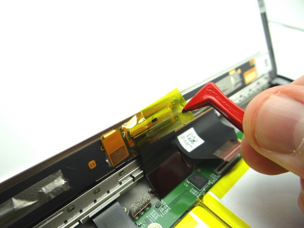
  11. Picture 1: Peel up yellow Kapton tape with plastic tweezers. Adhere the tape to the wall of COMPARTMENT A. You'll need a piece of Kapton tape for reassembly to help hold this display cable in place. Picture 2: Use the wide blue pry tool to open the brown bar of the ZIF connector.
    • Picture 1: Peel up yellow Kapton tape with plastic tweezers. Adhere the tape to the wall of COMPARTMENT A.

    • You'll need a piece of Kapton tape for reassembly to help hold this display cable in place.

    • Picture 2: Use the wide blue pry tool to open the brown bar of the ZIF connector.

    • Picture 3: Gently guide the cable out of the ZIF connector.

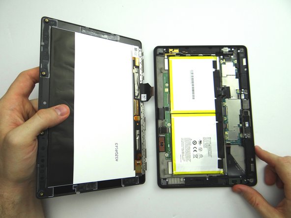
  12. Separate the Display Assembly from the Rear Case.  Place them in the sandbox.
    • Separate the Display Assembly from the Rear Case. Place them in the sandbox.

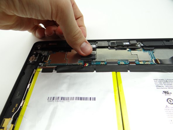
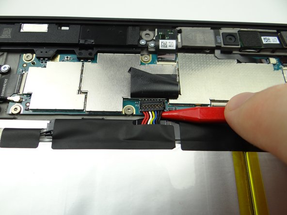
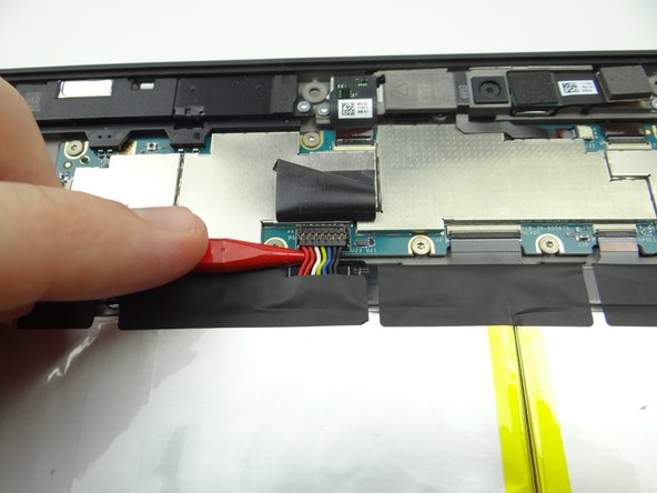
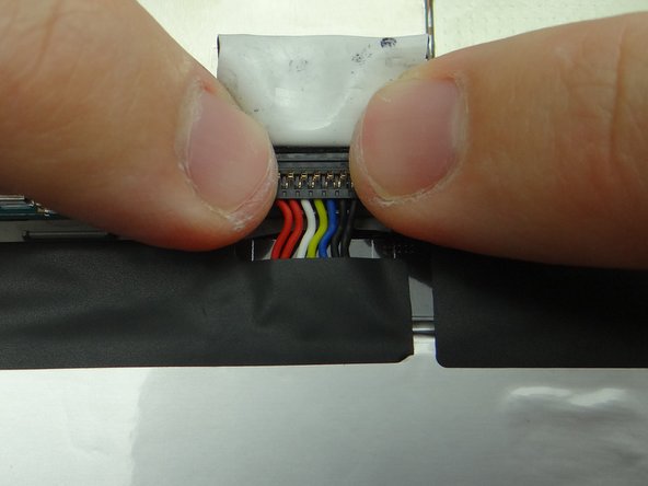
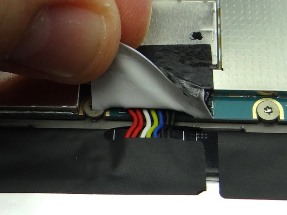
  13. Picture 1: Peel tape back to expose battery connector. Leave tape connected to the logic board as shown. Work slowly and carefully as you pry up the battery connector:
    • Picture 1: Peel tape back to expose battery connector.

    • Leave tape connected to the logic board as shown.

    • Work slowly and carefully as you pry up the battery connector:

    • Picture 2: Use the pointed end of the spudger to pry up right side of battery connector slightly.

    • Picture 3: Lift the battery connector straight up from the left side.

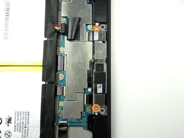
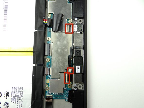
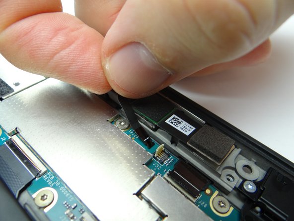
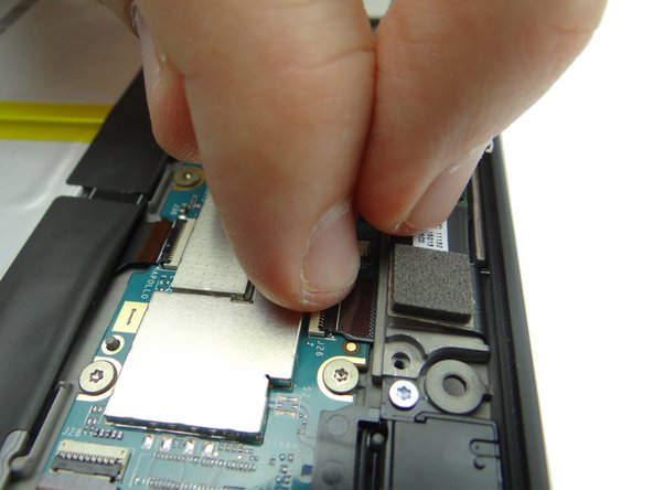
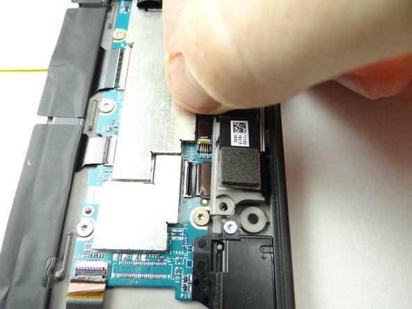
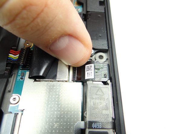
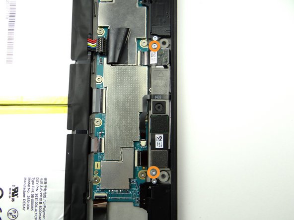
  14. Remove two 2.7mm T5 Torx screws and place in SLOT 2. In the next few steps, you'll disconnect: the front-facing camera cable, microphone cable and rear camera cable.
    • Remove two 2.7mm T5 Torx screws and place in SLOT 2.

    • In the next few steps, you'll disconnect: the front-facing camera cable, microphone cable and rear camera cable.

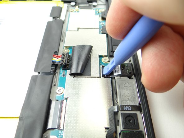
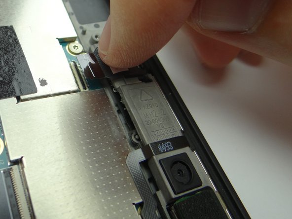
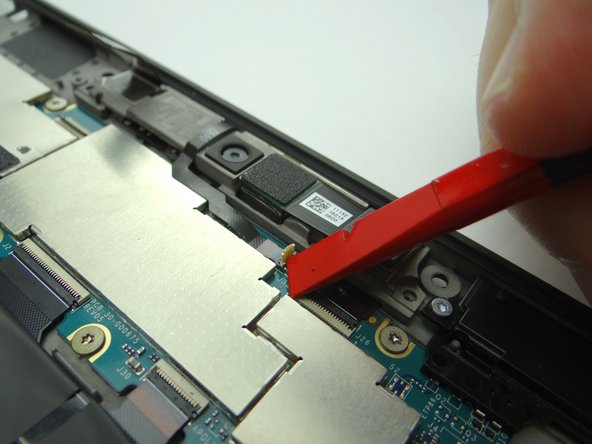
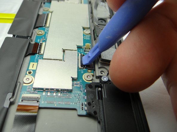
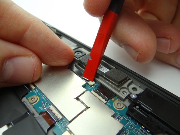
  15. Picture 1: Use the blue pry tool to open front-facing camera ZIF connector. Picture 2: Pull cable free with your fingers. Picture 3: Use the corner of the black spudger to open the small white microphone ZIF connector.
    • Picture 1: Use the blue pry tool to open front-facing camera ZIF connector.

    • Picture 2: Pull cable free with your fingers.

    • Picture 3: Use the corner of the black spudger to open the small white microphone ZIF connector.

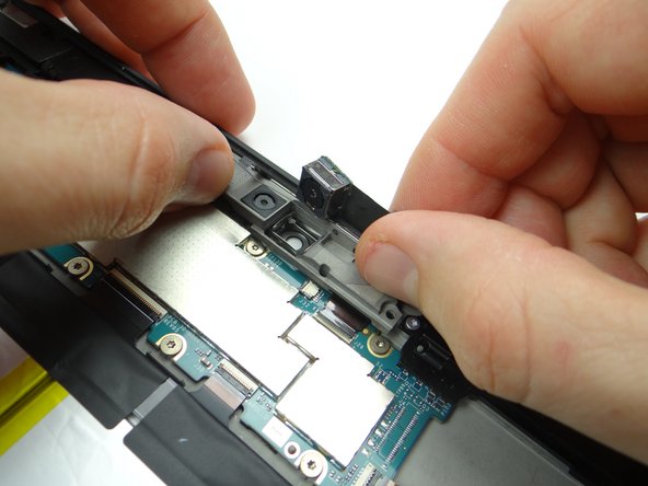
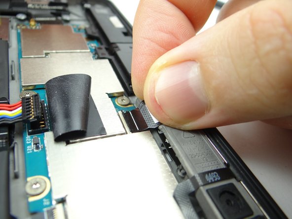
  16. Picture 1: Pull microphone cable free with your fingers. Picture 2: Use the blue pry tool to open rear camera ZIF connector. Picture 3: Swivel rear camera up from the socket.
    • Picture 1: Pull microphone cable free with your fingers.

    • Picture 2: Use the blue pry tool to open rear camera ZIF connector.

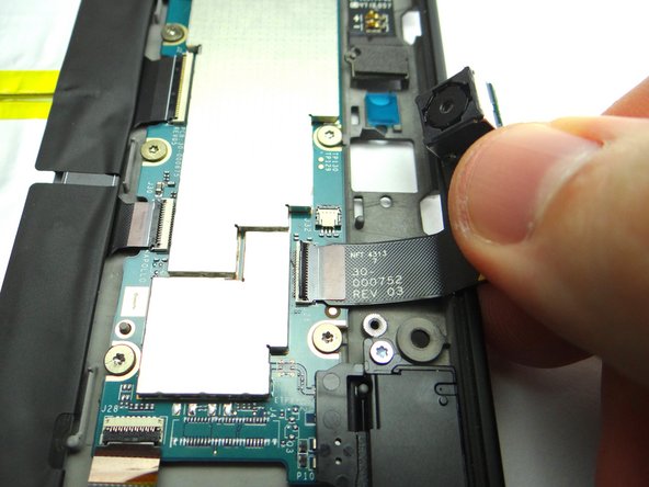
    • Picture 3: Swivel rear camera up from the socket.

    • Don't try to remove rear camera.

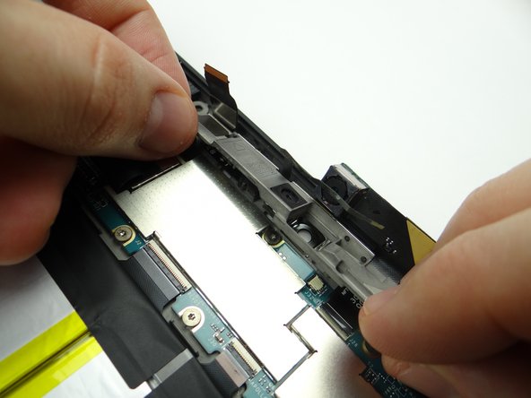
  17. Picture 1: Pivot bracket to a 45° angle, pull microphones away from their sockets on the rear case, then lift bracket away from Kindle. Picture 2: Place the bracket in sandbox. Picture 3: The rear camera stabilizer bracket may be loose.  If so, place it in COMPARTMENT D.
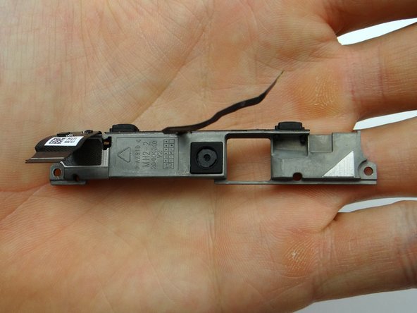
    • Picture 1: Pivot bracket to a 45° angle, pull microphones away from their sockets on the rear case, then lift bracket away from Kindle.

    • Picture 2: Place the bracket in sandbox.

    • Picture 3: The rear camera stabilizer bracket may be loose. If so, place it in COMPARTMENT D.

  18. Pull rear camera free from open ZIF connector.  Place in COMPARTMENT E.
    • Pull rear camera free from open ZIF connector. Place in COMPARTMENT E.

  19. From COMPARTMENT E, push rear camera cable into open ZIF connector.
    • From COMPARTMENT E, push rear camera cable into open ZIF connector.

  20. Replace rear camera stabilizer bracket from COMPARTMENT D.
    • Replace rear camera stabilizer bracket from COMPARTMENT D.

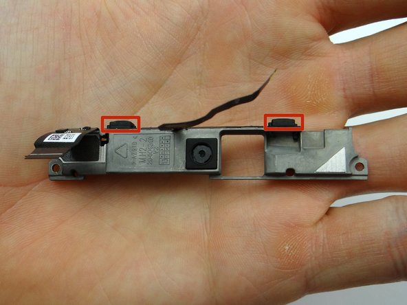
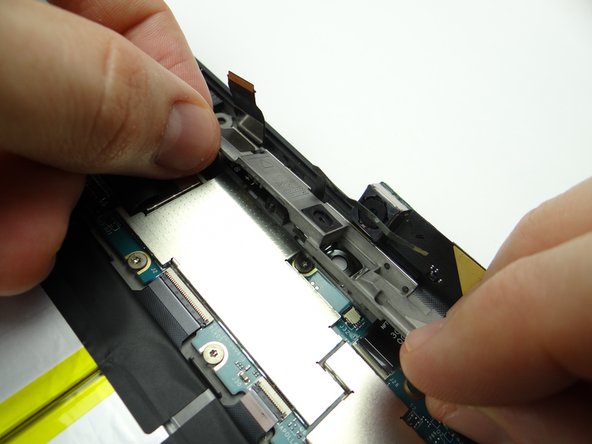
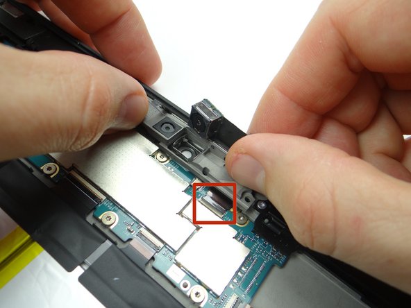
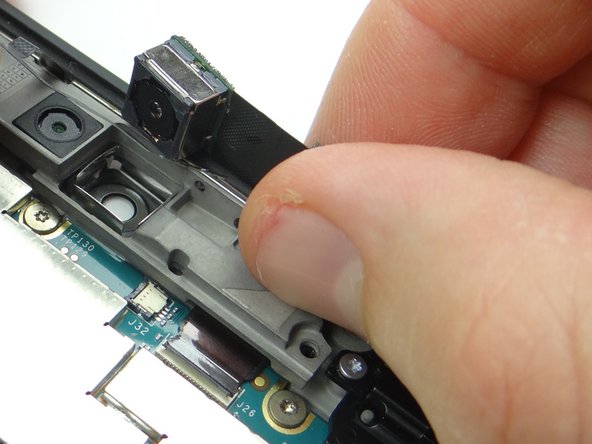
  21. Replace the microphones and cameras bracket: Picture 1 & 2: Carefully align the microphones marked in Picture 1 with the openings on the rear case. Picture 3: Make sure the rear camera cable is fully pushed into ZIF connector (red square) while continuing to position bracket into place.
    • Replace the microphones and cameras bracket:

    • Picture 1 & 2: Carefully align the microphones marked in Picture 1 with the openings on the rear case.

    • Picture 3: Make sure the rear camera cable is fully pushed into ZIF connector (red square) while continuing to position bracket into place.

  22. Push rear camera into its socket on the bracket. Close rear camera cable ZIF connector.
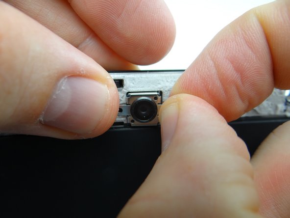
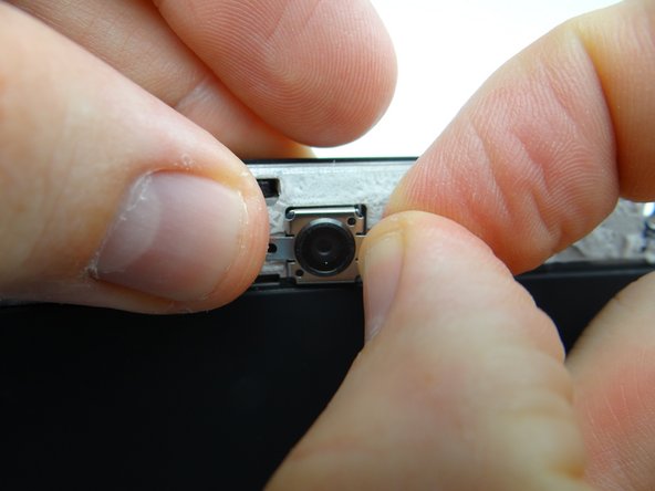
    • Push rear camera into its socket on the bracket.

    • Close rear camera cable ZIF connector.

  23. Insert the microphone cable into the ZIF connector. Hold the cable in place with your pointer finger while closing the ZIF connector using the flat end of the spudger.
    • Insert the microphone cable into the ZIF connector.

    • Hold the cable in place with your pointer finger while closing the ZIF connector using the flat end of the spudger.

  24. Picture 1: Insert the front-facing camera cable into the ZIF connector. Picture 2: Close the front-facing ZIF connector with your finger. Picture 3: Replace two 2.7mm T5 Torx screws from SLOT 2.
    • Picture 1: Insert the front-facing camera cable into the ZIF connector.

    • Picture 2: Close the front-facing ZIF connector with your finger.

    • Picture 3: Replace two 2.7mm T5 Torx screws from SLOT 2.

  25. Push battery connector straight down into its socket on the logic board. Fold down tape to cover the battery connector.
    • Push battery connector straight down into its socket on the logic board.

    • Fold down tape to cover the battery connector.

  26. Bring the display assembly to the rear case to attach the two display cables.
    • Bring the display assembly to the rear case to attach the two display cables.

  27. Picture 1: Insert the rectangular display cable into the ZIF connector. Picture 2: Close the ZIF connector with your finger. Picture 3: Cover ZIF connector with Kapton tape from COMPARTMENT A.
    • Picture 1: Insert the rectangular display cable into the ZIF connector.

    • Picture 2: Close the ZIF connector with your finger.

    • Picture 3: Cover ZIF connector with Kapton tape from COMPARTMENT A.

  28. Guide the triangular display cable into the ZIF connector using your finger. Close the ZIF connector.
    • Guide the triangular display cable into the ZIF connector using your finger.

    • Close the ZIF connector.

  29. Align the clips (red squares) along the bottom of the display assembly with their slots on the rear case.
    • Align the clips (red squares) along the bottom of the display assembly with their slots on the rear case.

  30. Pictures 1 & 2: Press the top of the display assembly firmly into the rear case to secure the clips along the top edge. Picture 3: Press firmly on the display assembly to ensure all clips are seated correctly. Picture 3: Press firmly on the display assembly to ensure all clips are seated correctly.
    • Pictures 1 & 2: Press the top of the display assembly firmly into the rear case to secure the clips along the top edge.

    • Picture 3: Press firmly on the display assembly to ensure all clips are seated correctly.

  31. Picture 1: Replace four pink 3.5 mm T5 Torx screws from SLOT 1. Picture 2: Replace the rear trim piece from ZONE I. Picture 3: Apply low level heat (100° Celcius) to help the adhesive re-adhere.
    • Picture 1: Replace four pink 3.5 mm T5 Torx screws from SLOT 1.

    • Picture 2: Replace the rear trim piece from ZONE I.

    • Picture 3: Apply low level heat (100° Celcius) to help the adhesive re-adhere.

  32. Power up and test the device.
    • Power up and test the device.

Finish Line
James Linder

Member since: 01/24/2013

71,591 Reputation

217 Guides authored

0 Comments

Add Comment

View Statistics:

Past 24 Hours: 0

Past 7 Days: 0

Past 30 Days: 0

All Time: 44

CELL PHONE SANDBOX