-
-
Power down the device.
-
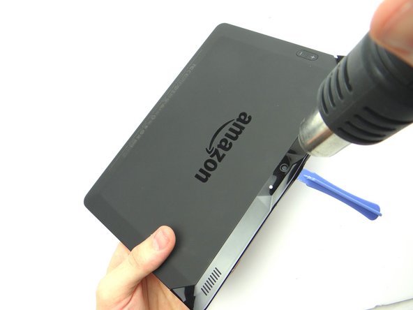
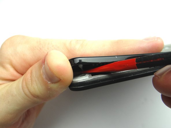
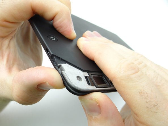
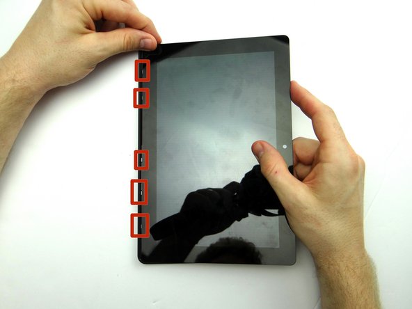
You'll be removing the trim (red square) in the next few steps:
-
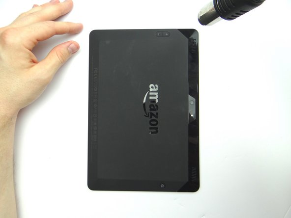
Apply low level heat (100° Celcius) to the corner of the trim.
-
-
-
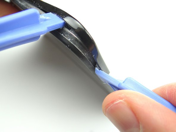
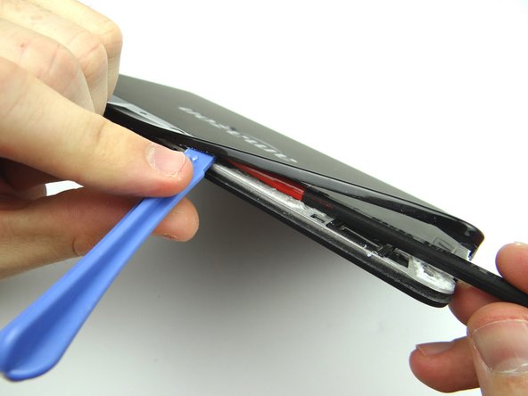
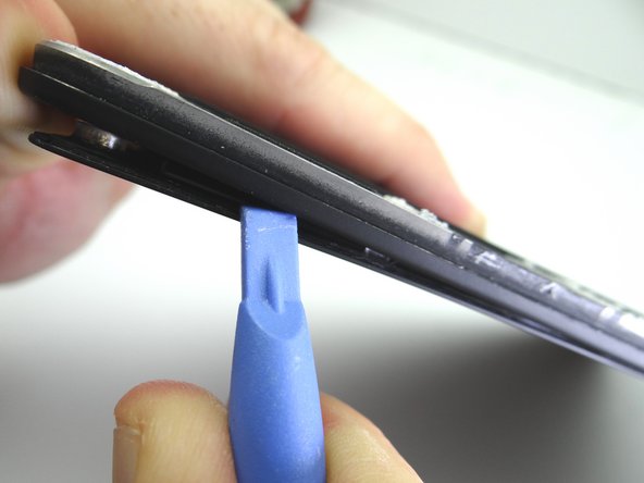
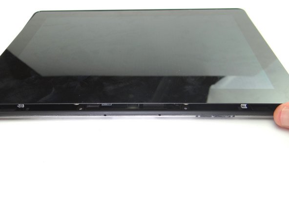
To begin removing the trim: insert blue pry tool face up between the rear camera and the corner.
-
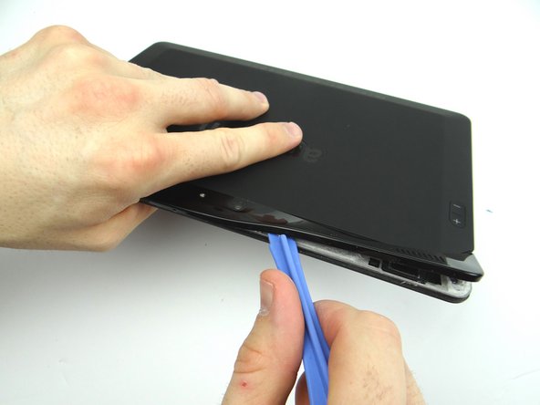
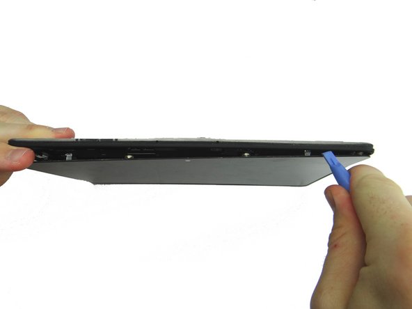
Insert a wide blue pry tool (just right of the first pry tool) and work towards the corner near the volume buttons.
-
-
-
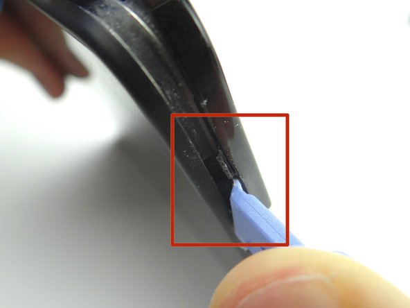
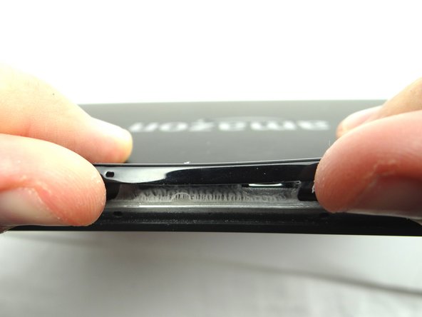
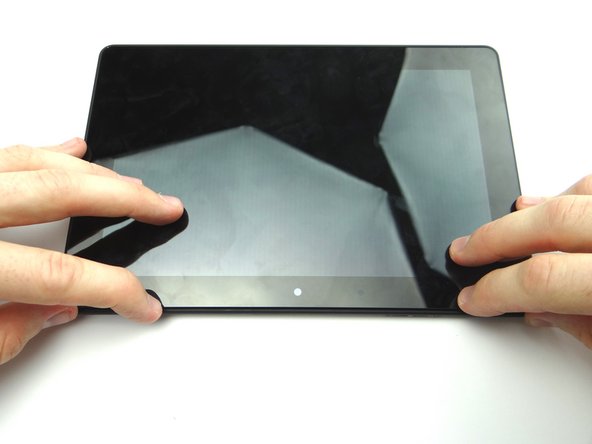
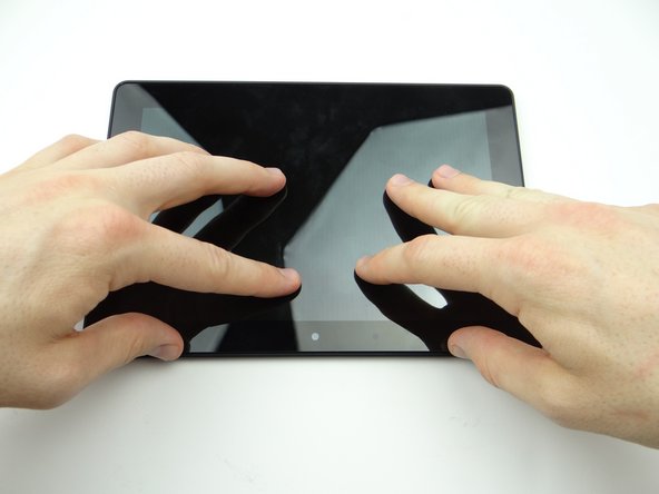
Pictures 1 & 2: Use a blue pry tool (face up) to pry up the bottom of the trim near the volume rocker. Gently pry up to release the tab (red square).
-
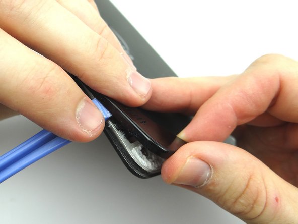
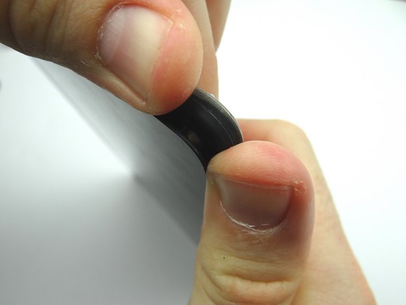
Picture 3: Using your fingers, gently pry up the corner of the rear trim.
-
-
-
Picture 1: Use the wide blue pry tool to work your way towards the camera.
-
Picture 2: Apply heat as needed.
-
Picture 3: Use the flat end of the spudger to cut through adhesive.
-
-
-
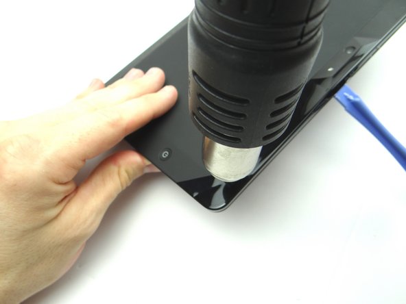
Apply low level heat (100° Celcius) from the center to the power button.
-
Work your way towards the corner.
-
-
-
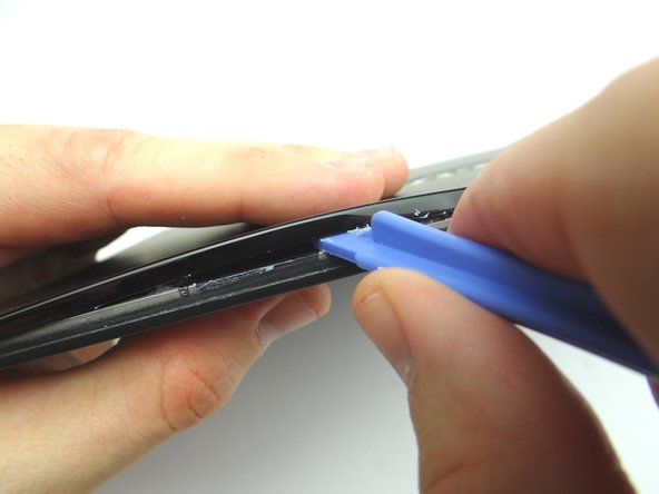
Gently lift the trim using your fingers to expose the remaining adhesive.
-
Use the flat end of the spudger to cut through it.
-
-
-
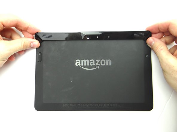
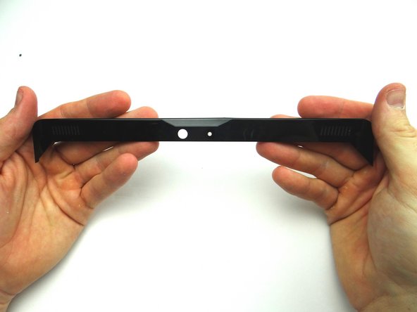
Picture 1 & 2: Finish removing the rear trim with your fingers and place in ZONE I.
-
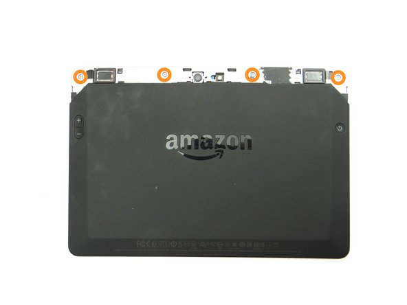
Picture 3: Remove four pink 3.5 mm T5 Torx screws. Place in SLOT 1.
-
-
-
Pictures 1 & 2: Using your thumbs, apply pressure to the rear case in the corner near the power button to begin separating the display assembly from the rear case.
-
Picture 3: Insert a blue pry tool along the top edge between the display assembly and rear case.
-
-
-
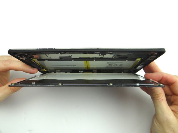
Picture 1: Hold the corner open with your finger while using the blue pry tool to release the clips along the top of the display assembly.
-
Picture 2: Open the screen like a book until all clips are released.
-
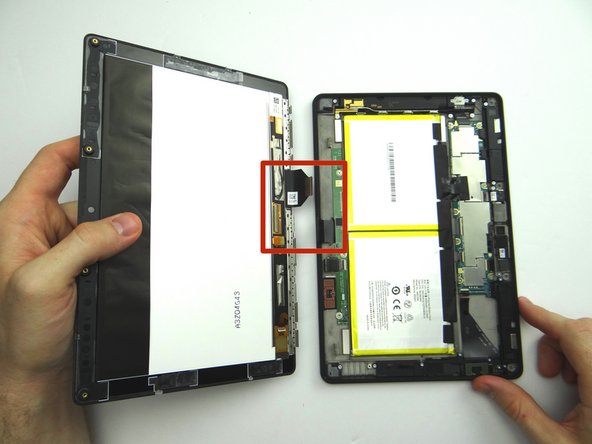
Picture 3: Lay the rear case on the table with the display assembly open at a 90° angle, as shown.
-
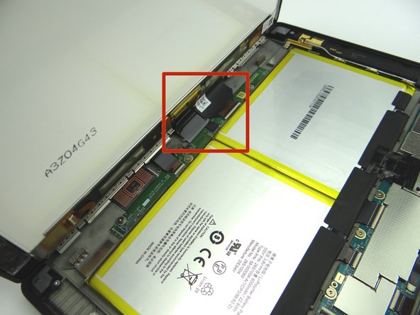
In the next couple step you'll release the display cables (red square):
-
-
-
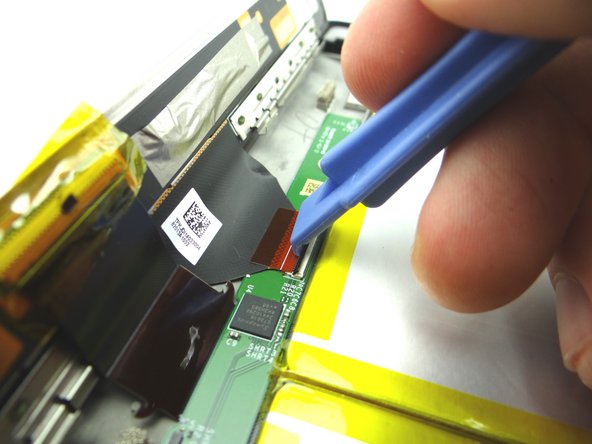
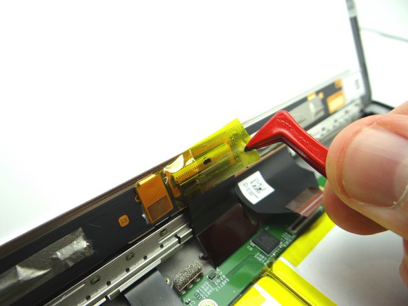
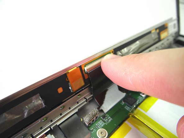
Use the wide blue pry tool to move the ZIF connector black bar into open position as shown.
-
Gently guide the display cable out of the ZIF connector.
-
-
-
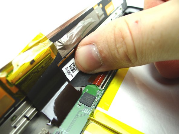
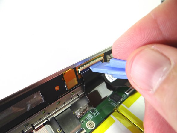
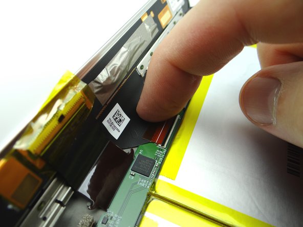
Picture 1: Peel up yellow Kapton tape with plastic tweezers. Adhere the tape to the wall of COMPARTMENT A.
-
You'll need a piece of Kapton tape for reassembly to help hold this display cable in place.
-
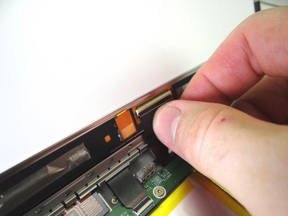
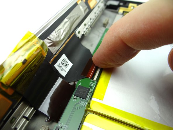
Picture 2: Use the wide blue pry tool to open the brown bar of the ZIF connector.
-
Picture 3: Gently guide the cable out of the ZIF connector.
-
-
-
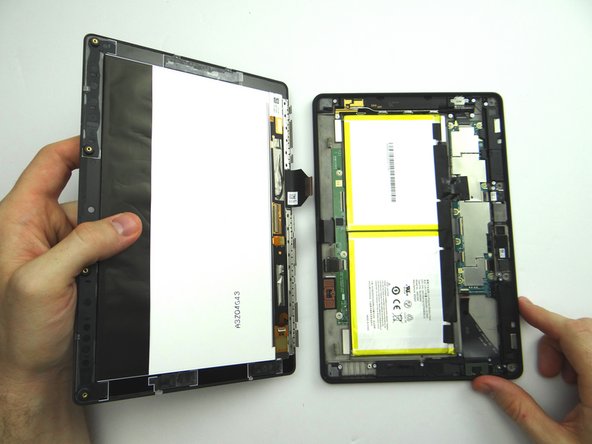
Separate the Display Assembly from the Rear Case. Place them in the sandbox.
-
-
-
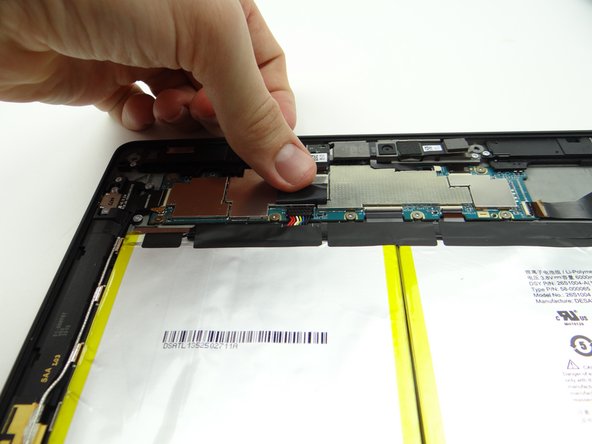
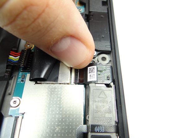
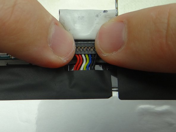
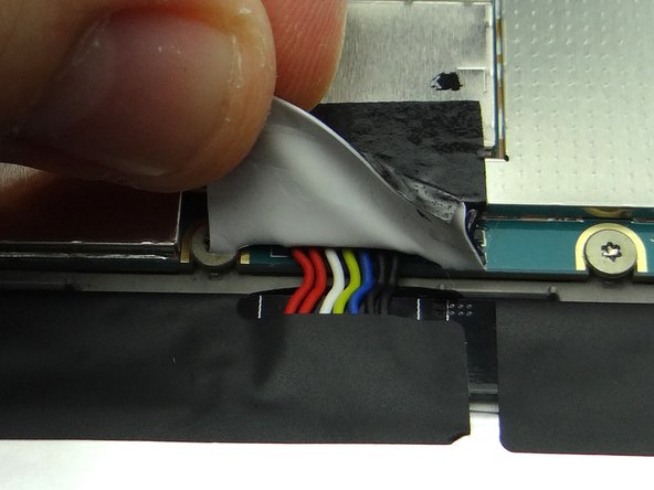
Picture 1: Peel tape back to expose battery connector.
-
Leave tape connected to the logic board as shown.
-
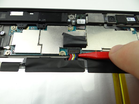
Work slowly and carefully as you pry up the battery connector:
-
Picture 2: Use the pointed end of the spudger to pry up right side of battery connector slightly.
-
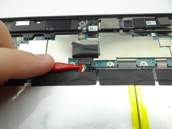
Picture 3: Lift the battery connector straight up from the left side.
-
-
-
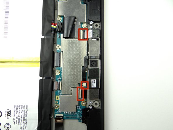
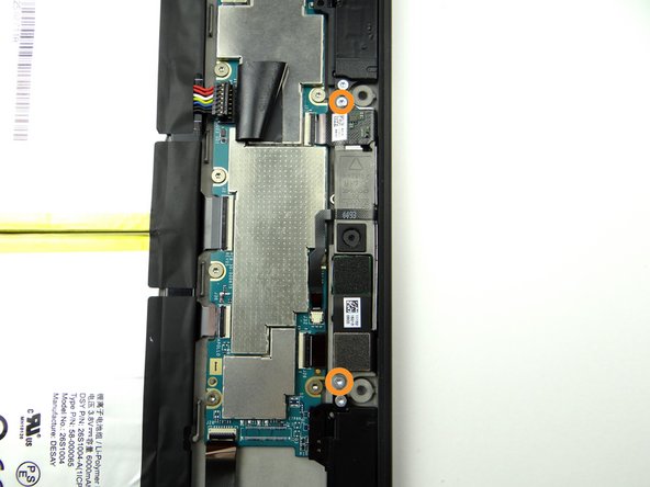
Remove two 2.7mm T5 Torx screws and place in SLOT 2.
-
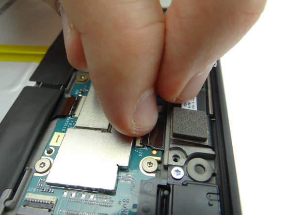
In the next few steps, you'll disconnect: the front-facing camera cable, microphone cable and rear camera cable.
-
-
-
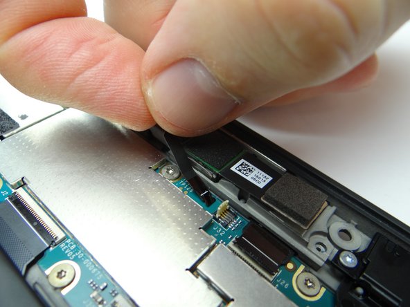
Picture 1: Use the blue pry tool to open front-facing camera ZIF connector.
-
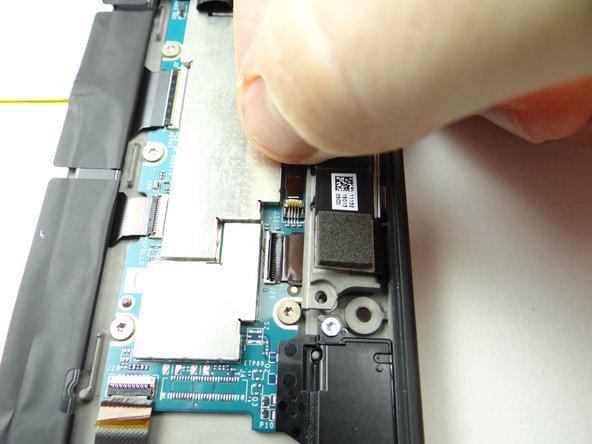
Picture 2: Pull cable free with your fingers.
-
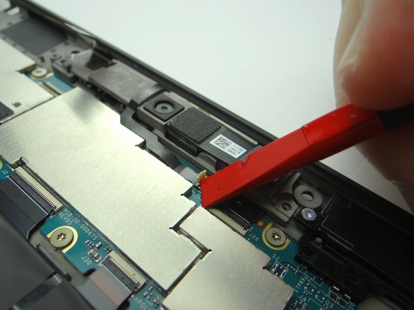
Picture 3: Use the corner of the black spudger to open the small white microphone ZIF connector.
-
-
-
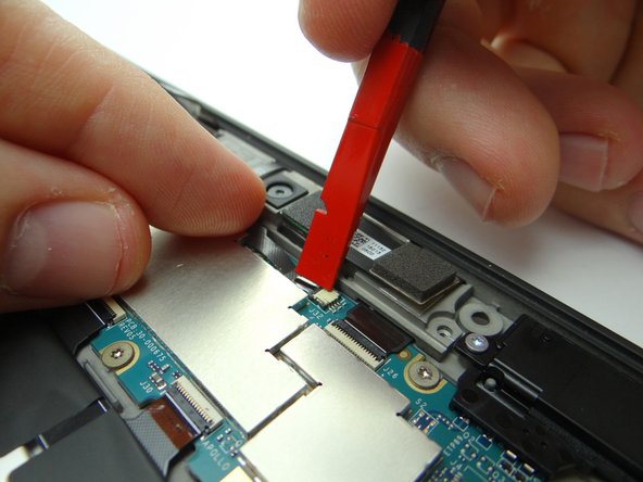
Picture 1: Pull microphone cable free with your fingers.
-
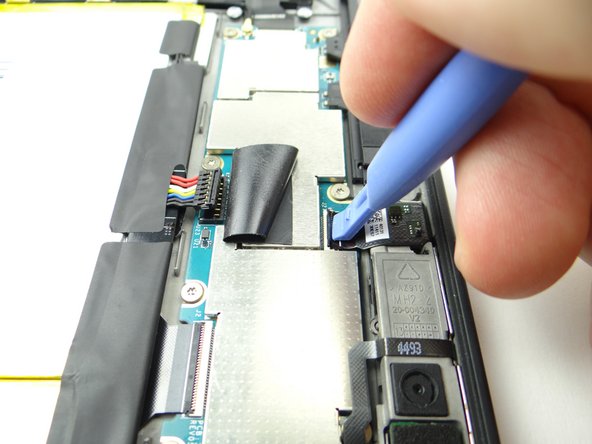
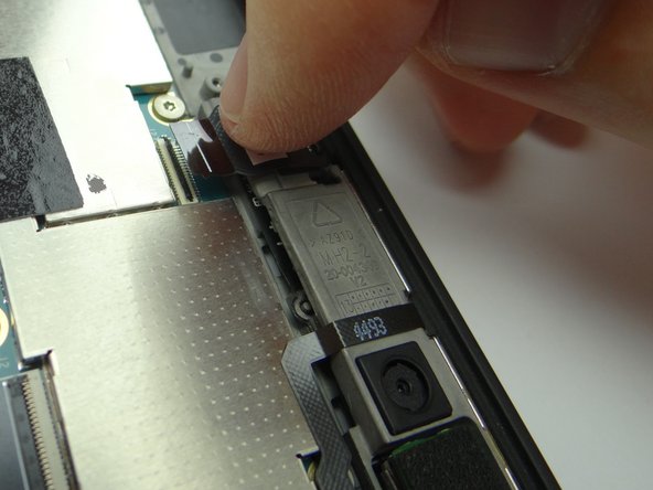
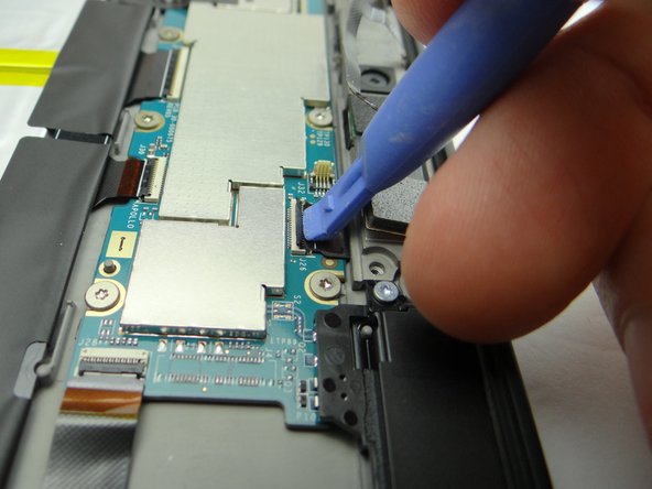
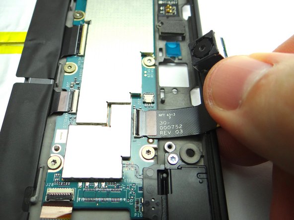
Picture 2: Use the blue pry tool to open rear camera ZIF connector.
-
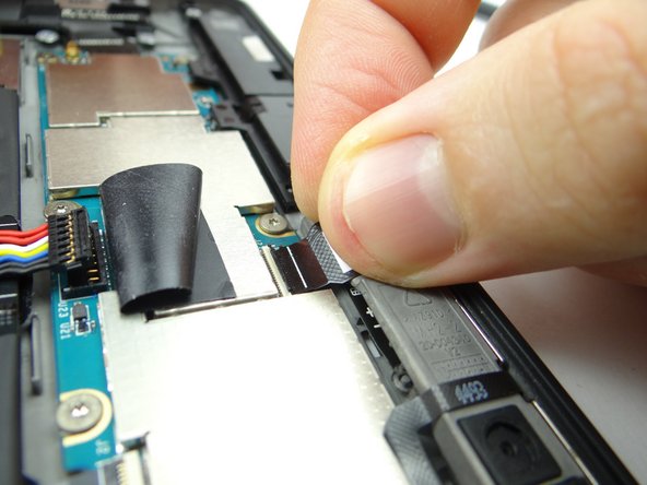
Picture 3: Swivel rear camera up from the socket.
-
Don't try to remove rear camera.
-
-
-
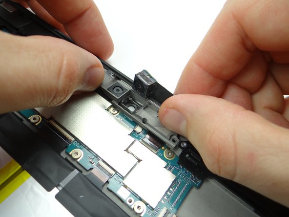
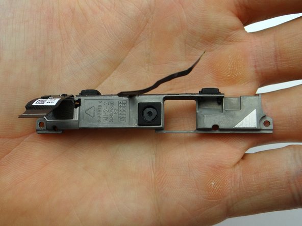
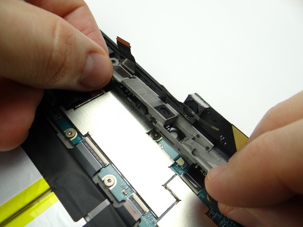
Picture 1: Pivot bracket to a 45° angle, pull microphones away from their sockets on the rear case, then lift bracket away from Kindle.
-
Picture 2: Place the bracket in sandbox.
-
Picture 3: The rear camera stabilizer bracket may be loose. If so, place it in COMPARTMENT D.
-
-
-
Pull rear camera free from open ZIF connector. Place in COMPARTMENT E.
-
-
-
From COMPARTMENT E, push rear camera cable into open ZIF connector.
-
-
-
Replace rear camera stabilizer bracket from COMPARTMENT D.
-
-
-
Replace the microphones and cameras bracket:
-
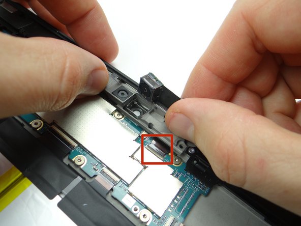
Picture 1 & 2: Carefully align the microphones marked in Picture 1 with the openings on the rear case.
-
Picture 3: Make sure the rear camera cable is fully pushed into ZIF connector (red square) while continuing to position bracket into place.
-
-
-
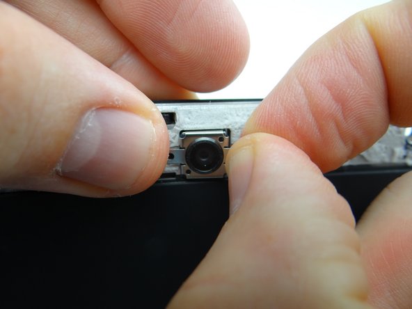
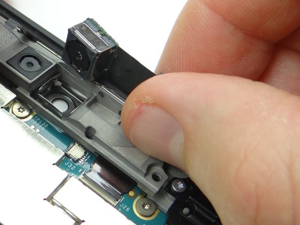
Push rear camera into its socket on the bracket.
-
Close rear camera cable ZIF connector.
-
-
-
Insert the microphone cable into the ZIF connector.
-
Hold the cable in place with your pointer finger while closing the ZIF connector using the flat end of the spudger.
-
-
-
Picture 1: Insert the front-facing camera cable into the ZIF connector.
-
Picture 2: Close the front-facing ZIF connector with your finger.
-
Picture 3: Replace two 2.7mm T5 Torx screws from SLOT 2.
-
-
-
Push battery connector straight down into its socket on the logic board.
-
Fold down tape to cover the battery connector.
-
-
-
Bring the display assembly to the rear case to attach the two display cables.
-
-
-
Picture 1: Insert the rectangular display cable into the ZIF connector.
-
Picture 2: Close the ZIF connector with your finger.
-
Picture 3: Cover ZIF connector with Kapton tape from COMPARTMENT A.
-
-
-
Guide the triangular display cable into the ZIF connector using your finger.
-
Close the ZIF connector.
-
-
-
Align the clips (red squares) along the bottom of the display assembly with their slots on the rear case.
-
-
-
Pictures 1 & 2: Press the top of the display assembly firmly into the rear case to secure the clips along the top edge.
-
Picture 3: Press firmly on the display assembly to ensure all clips are seated correctly.
-
-
-
Picture 1: Replace four pink 3.5 mm T5 Torx screws from SLOT 1.
-
Picture 2: Replace the rear trim piece from ZONE I.
-
Picture 3: Apply low level heat (100° Celcius) to help the adhesive re-adhere.
-
-
-
Power up and test the device.
-