-
-
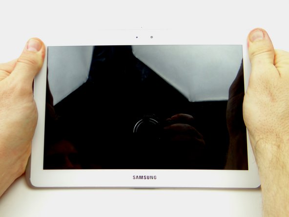
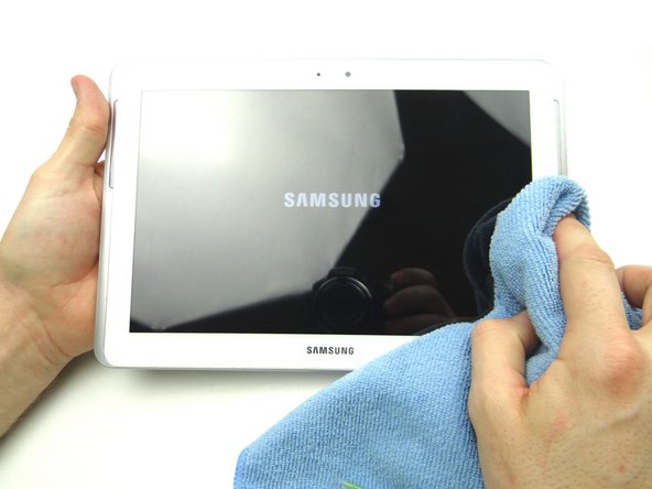
Power down the device.
-
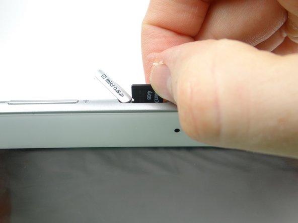
Remove SD card and place in COMPARTMENT A.
-
-
-
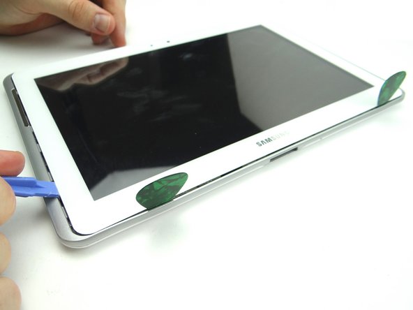
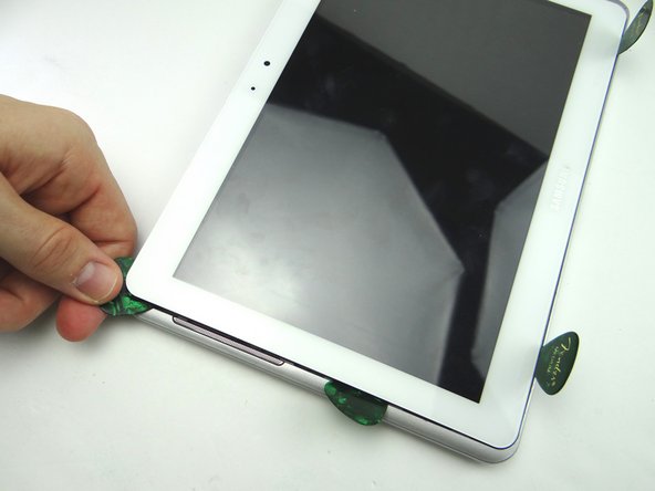
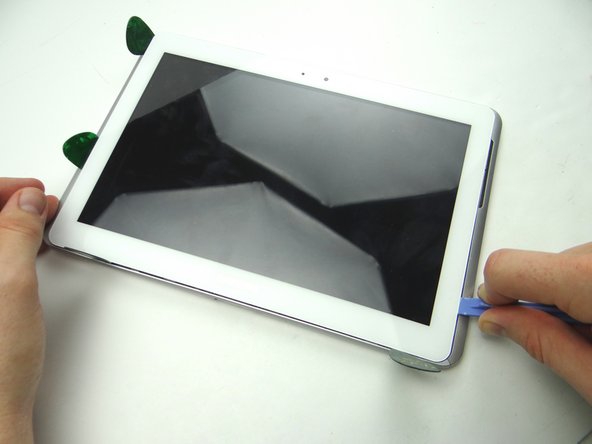
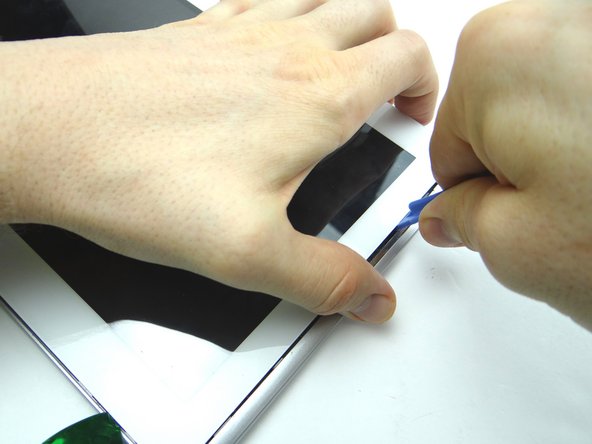
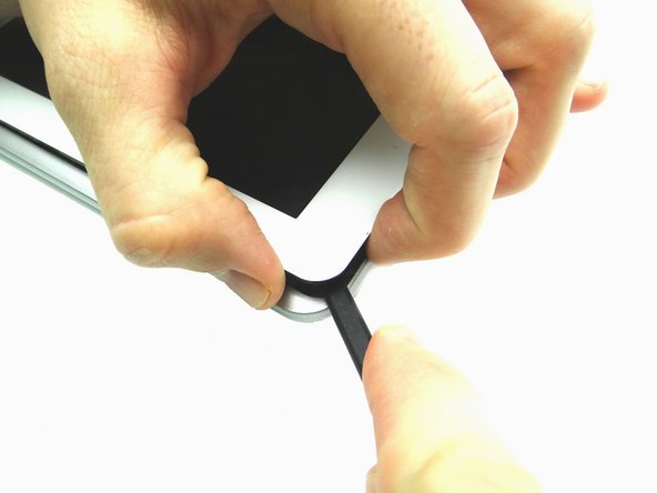
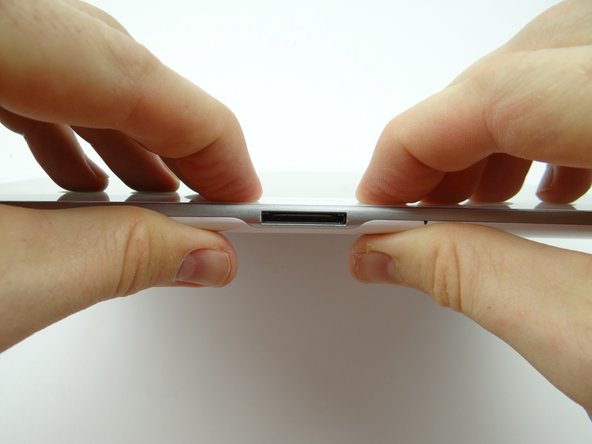
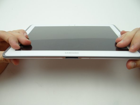
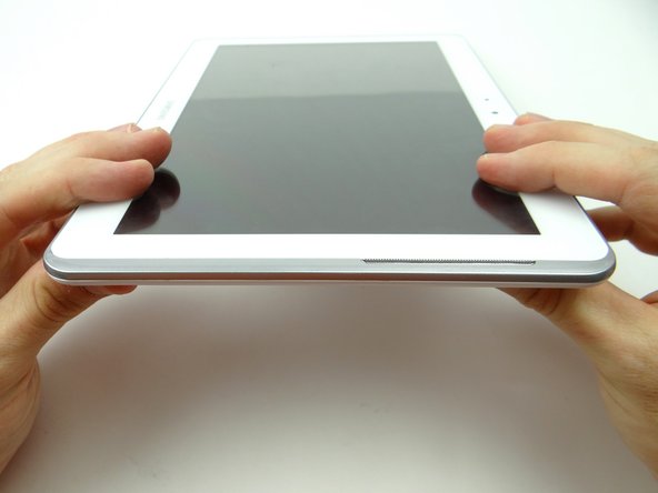
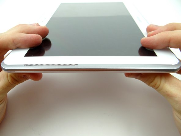
Pictures 1 & 2: Insert a wide blue pry tool between the rear case and front panel at the bottom of the tablet, an inch left of the Samsung logo. Sweep left, then insert a guitar pick to hold the left side open. Work your way right with the blue pry tool.
-
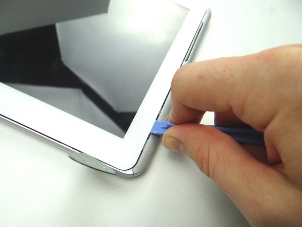
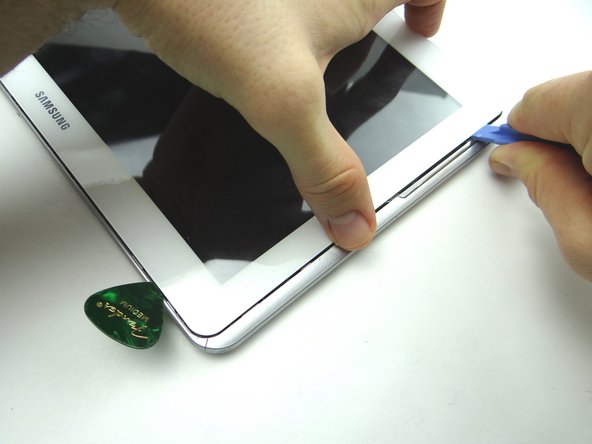
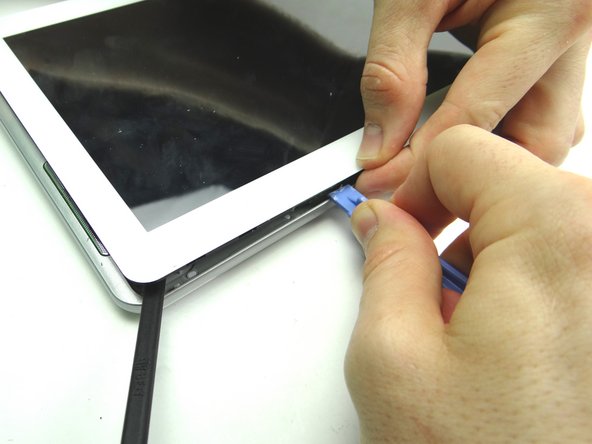
Picture 3: Insert a guitar pick to hold the right side open.
-
-
-
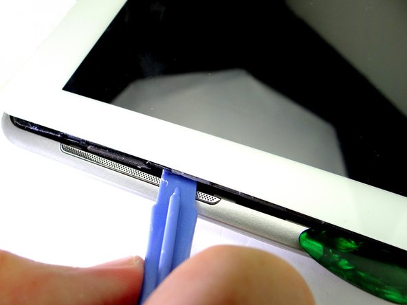
Picture 1: Insert the blue pry tool in the lower-left corner.
-
Picture 2: Work your way up to the speaker. Insert a guitar pick an inch below the speaker.
-
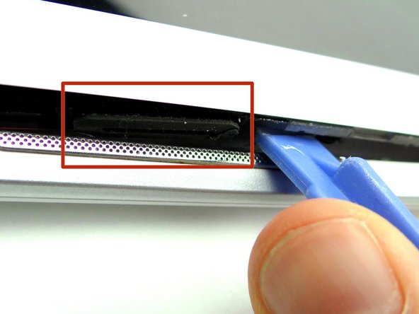
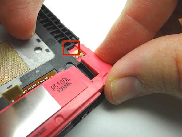
Picture 3: Continue prying up until you can see the rubber piece on the speaker (red square).
-
-
-
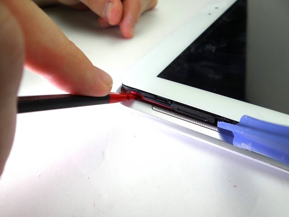
Picture 1: Use spudger to pry up upper-left corner under the pink speaker.
-
Picture 2: Put a guitar pick in place of the spudger to hold the upper-left corner open.
-
-
-
Picture 1: Insert the blue pry tool in the lower-right corner.
-
Picture 2: Slowly work your way up with the blue pry tool, pivoting the front panel slightly up from the rear case.
-
Picture 3: Create just enough space to hold the front panel just above the rear case with your fingers.
-
-
-
Pictures 1 & 2: Continue lifting the upper-right corner until you can wedge the flat end of a spudger in the upper-right corner to hold it open.
-
Picture 3: Sweep across the top with the blue pry tool, while gently pulling up the front panel with your fingers.
-
-
-
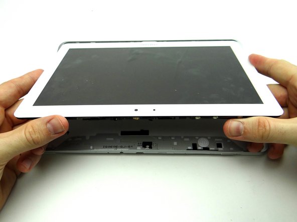
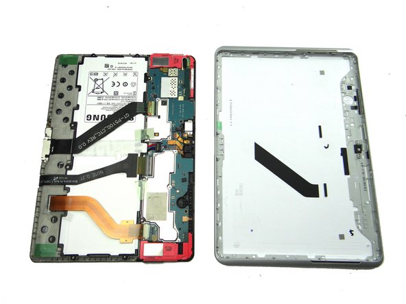
Remove the blue pry tools, then pivot the top edge of the front panel above the rear case.
-
Once the top edge reaches a 45° angle, pull it away from the rear case.
-
-
-
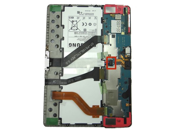
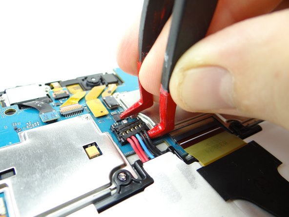
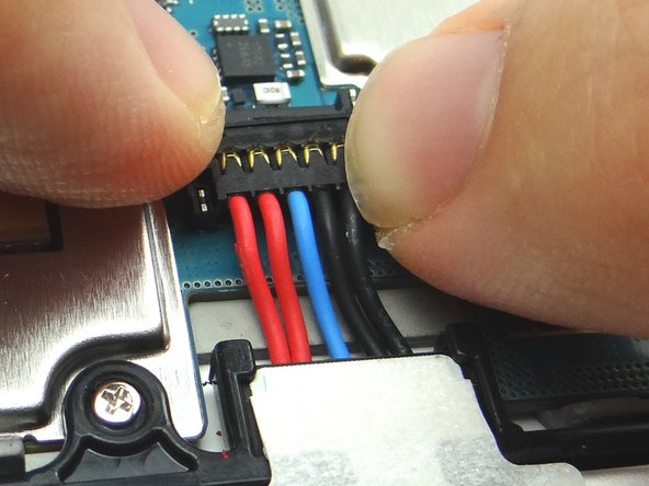
Battery cable head is fragile:
-
Use one prong of the plastic tweezers to wedge under the right side of the battery connector and pull it up slightly.
-
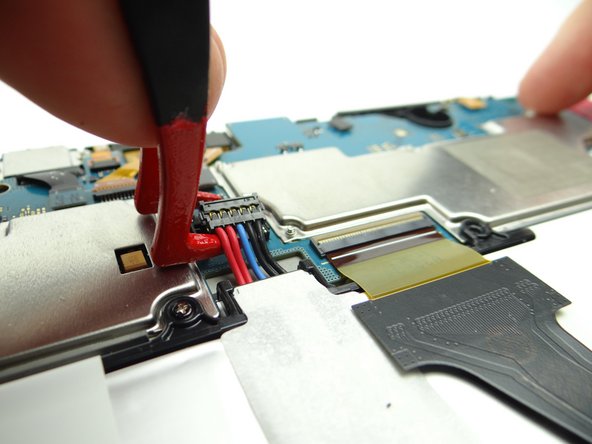
Lift battery connector straight up from the left side to dislodge it.
-
-
-
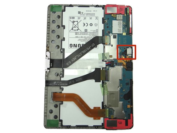
Remove the headset jack:
-
Use blue pry tool to disconnect headset jack cable.
-
Remove two 3.0 mm #00 Phillips screws from the headset jack. Place screws in SLOT 1.
-
-
-
Pictures 1 & 2: Use the pointed tip of the spudger to lift the headset jack out of its socket.
-
Place in COMPARTMENT B.
-
-
-
Use blue pry tool to open ZIF connector holding the infrared sensor cable.
-
With the ZIF connector open, use your finger to pull the cable free.
-
-
-
Adhesive holds the infrared cable in place:
-
Use the flat end of the spudger to separate the cable from the frame.
-
Place in COMPARTMENT C.
-
-
-
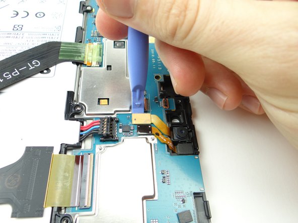
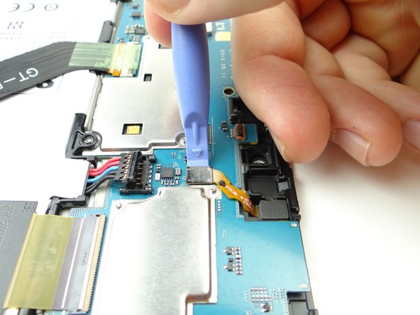
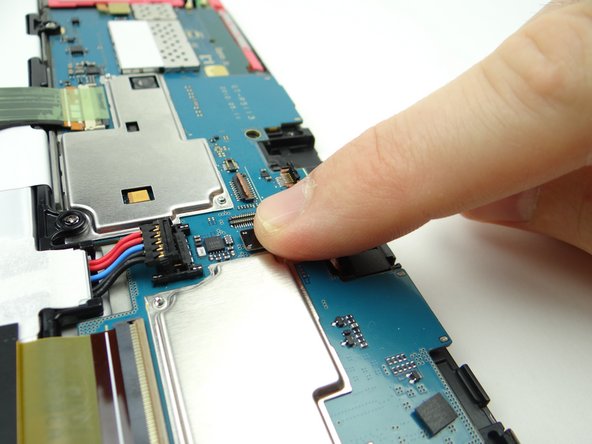
Picture 1: Use the blue pry tool to push ZIF connector open.
-
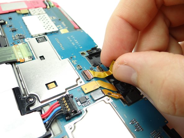
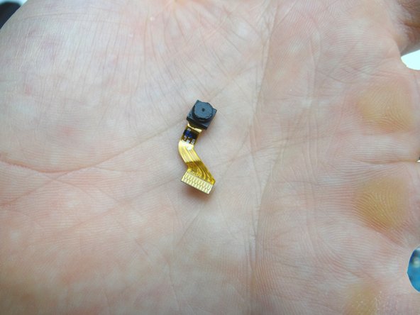
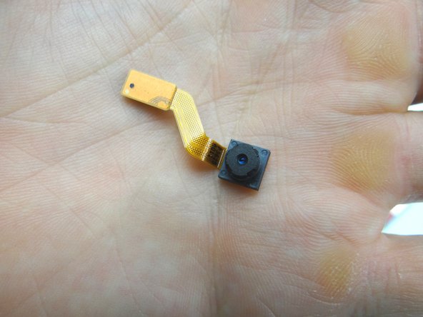
Picture 2: Lift front camera from its socket, then away from the ZIF connector.
-
Picture 3: Place in COMPARTMENT C.
-
-
-
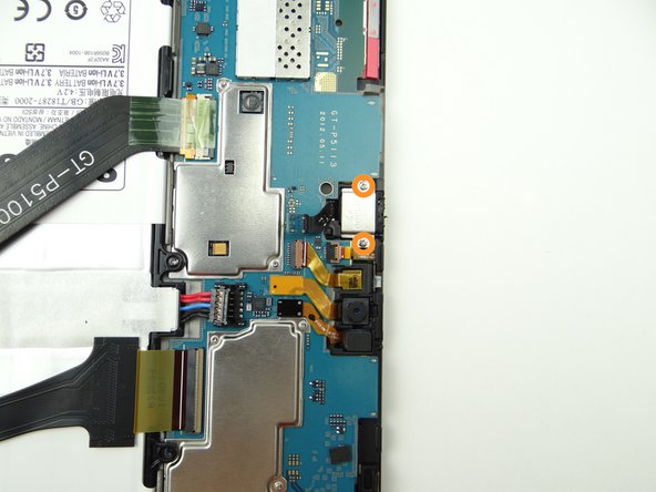
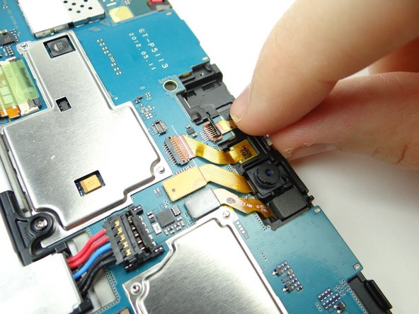
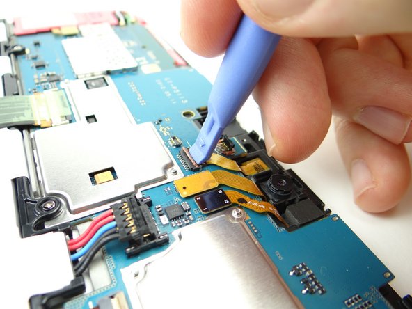
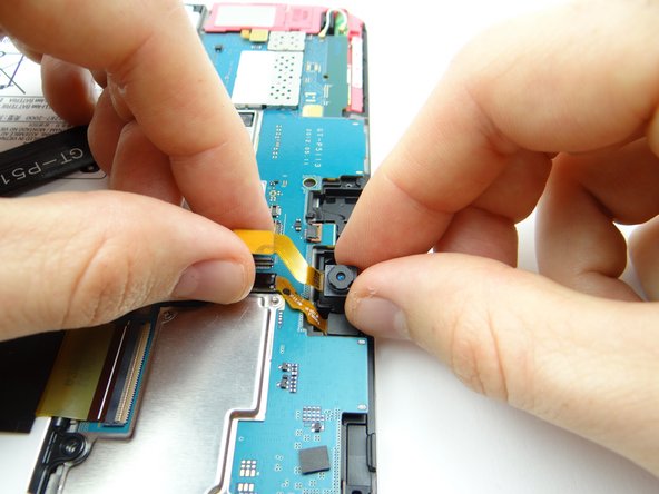
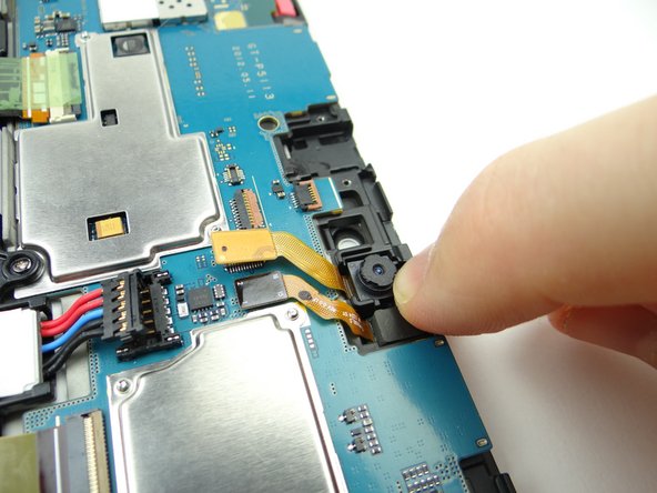
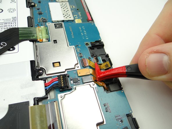
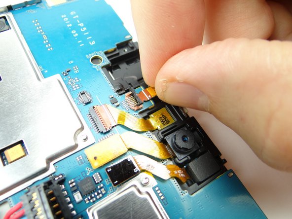
Use blue pry tool to disconnect rear camera.
-
Remove rear camera and place in COMPARTMENT D.
-
-
-
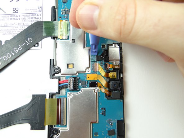
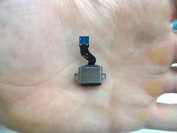
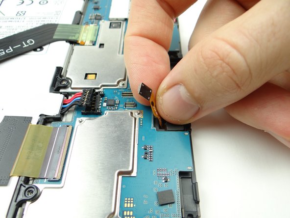
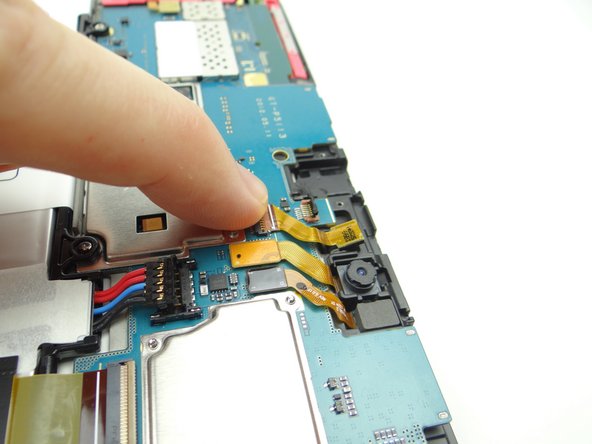
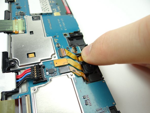
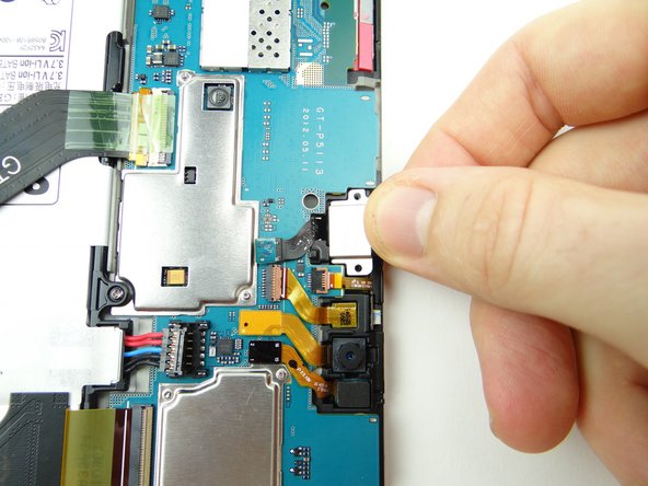
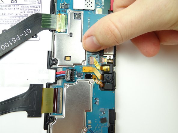
Picture 1: Use blue pry tool to disconnect sensor cable.
-
Picture 2: Pinch cable as close to sensor as possible and gently pull it free.
-
Picture 3: Place sensor in COMPARTMENT D.
-
-
-
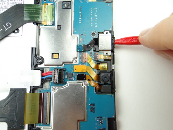
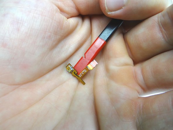
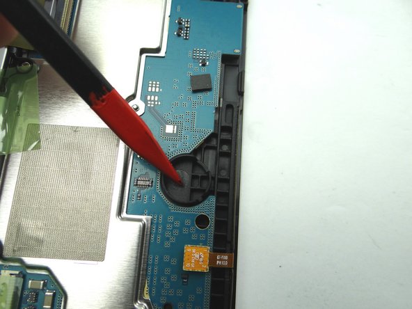
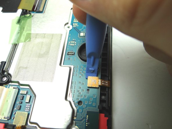
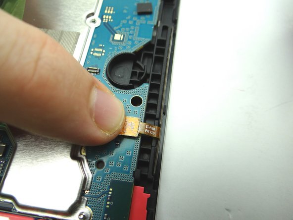
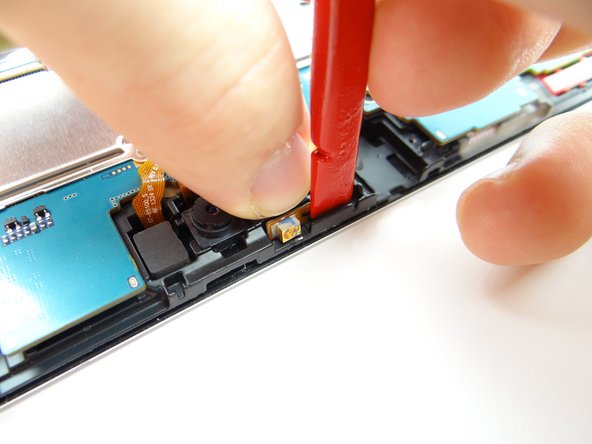
Picture 1: Use blue pry tool to disconnect vibrator cable.
-
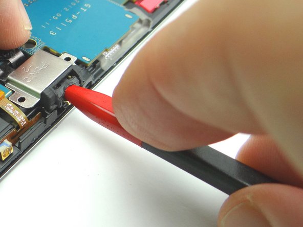
Picture 2: Use curved-tip tweezers in the closed position to wedge underneath the vibrator. Pry it up slightly then grab it with your fingers to finish removing it.
-
Picture 3: Place it in COMPARTMENT F.
-
-
-
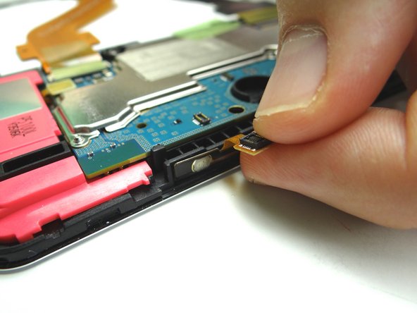
Picture 1: Use blue pry tool to disconnect power / volume buttons cable.
-
Adhesive holds the power & volume buttons cable in place:
-
Picture 2: Use the flat end of the spudger to separate the cable from the frame.
-
Picture 3: Place power & volume buttons cable in COMPARTMENT E.
-
-
-
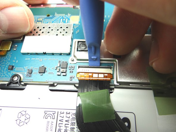
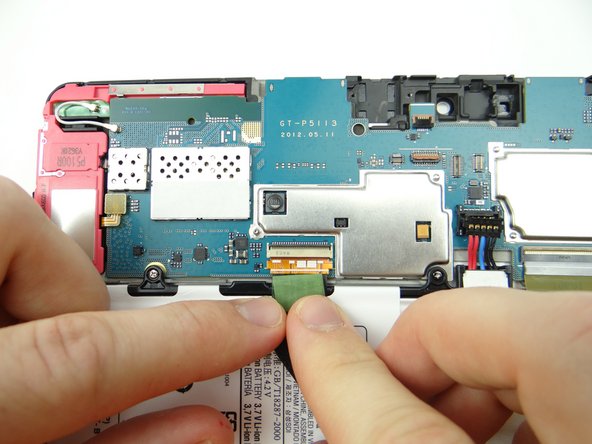
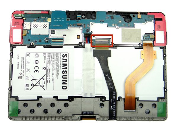
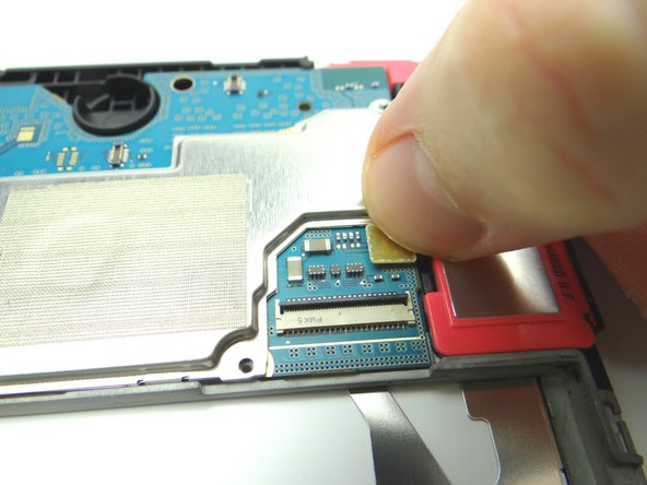
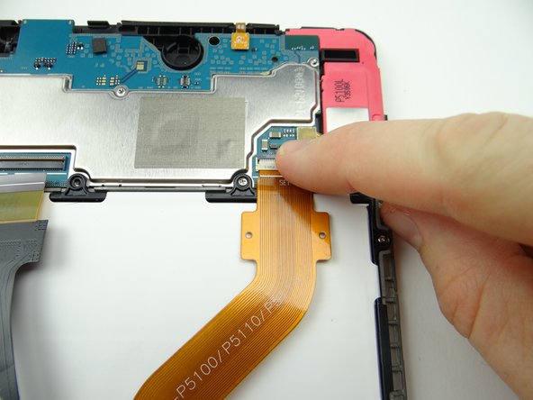
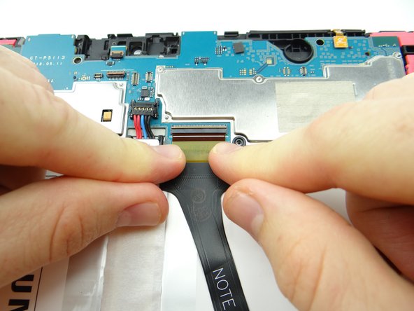
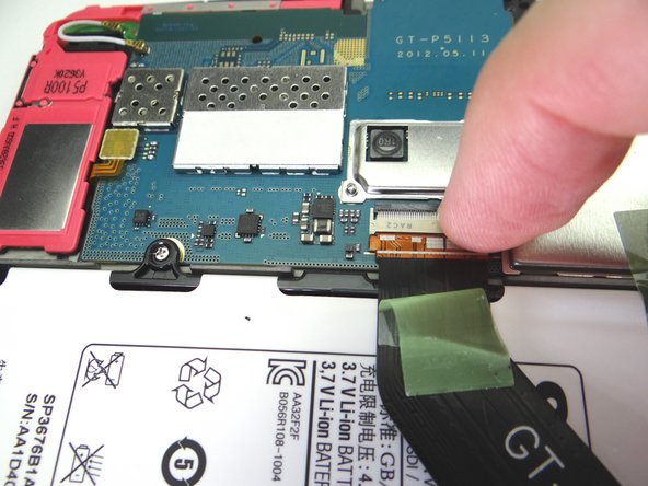
Picture 1: Peel tape up from connector and fold it back. Don't discard it - leave it attached to the cable.
-
Picture 2: Use blue pry tool to lift ZIF connector black bar into open position.
-
Picture 3: Slide cable out with your fingers.
-
-
-
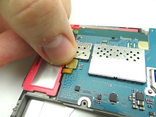
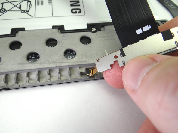
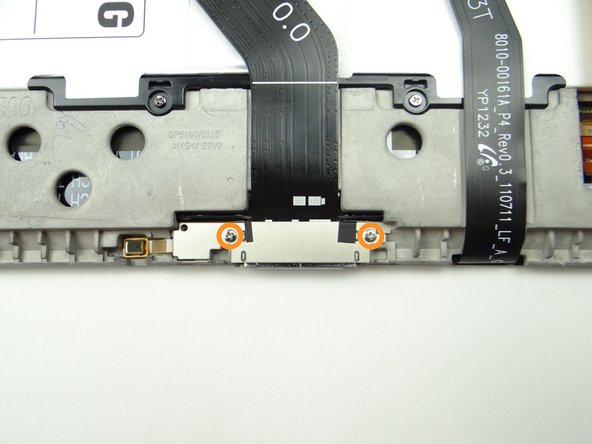
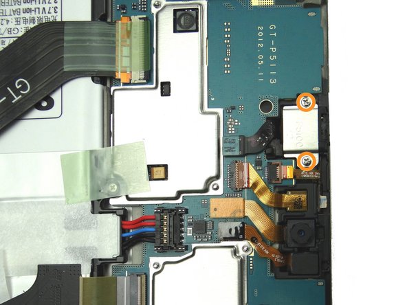
Picture 1: Remove two 2.9 mm #00 Phillips screws securing charging port. Place in SLOT 2.
-
Adhesive holds the microphone (attached to the charging port) in place:
-
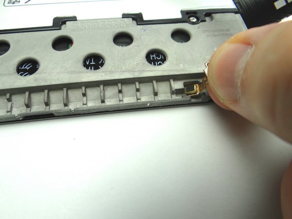
Pictures 2: Pull up the right side of the charging port until the microphone starts to stick. Pinch the microphone with your fingers and peel it up.
-
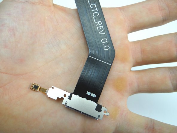
Picture 3: Place charging port / microphone assembly in ZONE V.
-
-
-
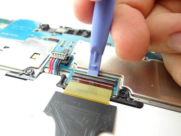
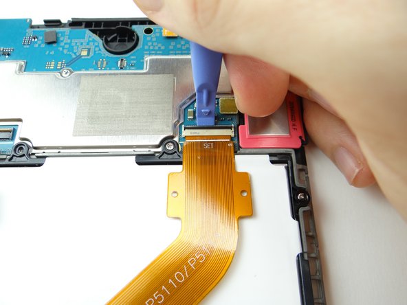
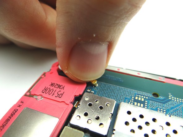
Use blue pry tool to lift the cream-colored digitizer ZIF connector bar into open position.
-
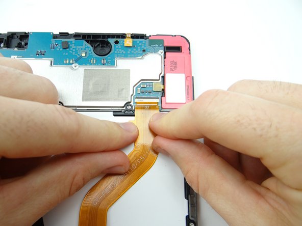
Slide cable out with your fingers.
-
-
-
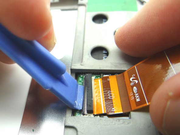
Use blue pry tool to lift the black LCD ZIF connector bar into open position.
-
Pull cable free with your fingers.
-
-
-
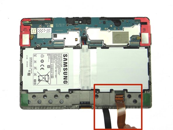
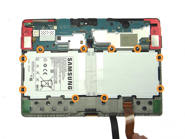
Hold LCD and digitizer cables out of the way while removing the battery screws.
-
Remove ten 3.0 mm #00 Phillips screws holding the battery. Place screws in SLOT 3.
-
-
-
The battery lifts easily up and away from the tablet. Place battery in ZONE V.
-
-
-
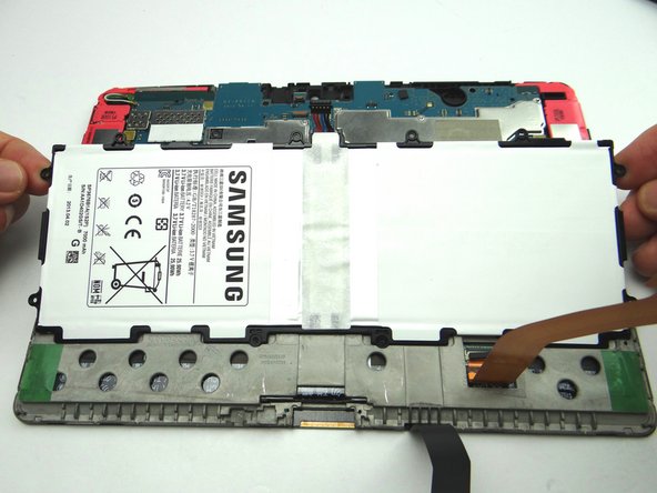
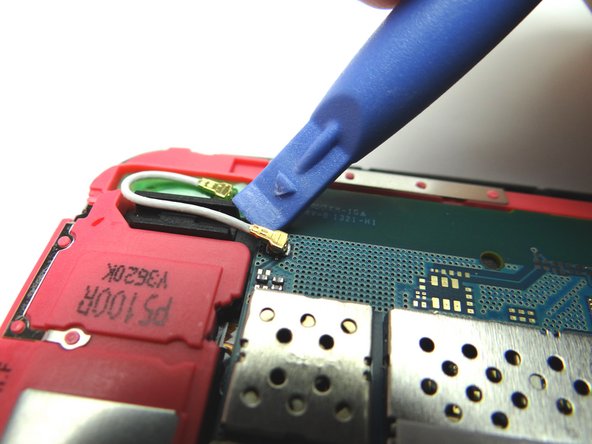
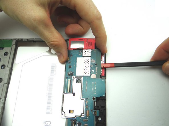
Picture 1: Use blue pry tool to disconnect antenna from logic board. Leave antenna connected to the loudspeaker.
-
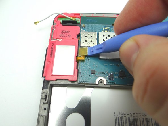
Picture 2: Use blue pry tool to disconnect loudspeaker from logic board.
-
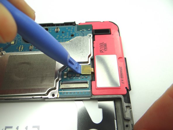
Picture 3: Use blue pry tool to disconnect opposite loudspeaker from logic board.
-
-
-
The logic board should come up easily:
-
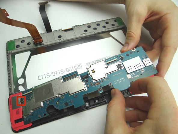
Picture 1: Wedge the flat end of the spudger under the top edge of the logic board as shown. Pry up just enough to pinch the logic board with your fingers.
-
Picture 2: Carefully continue lifting logic board away from the front panel.
-
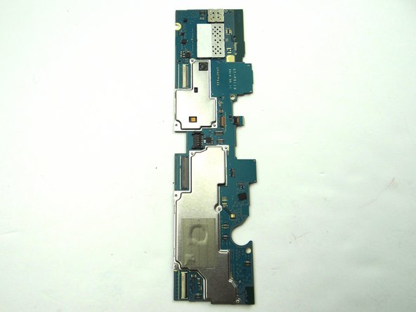
Picture 3: Place in ZONES I & II.
-
-
-
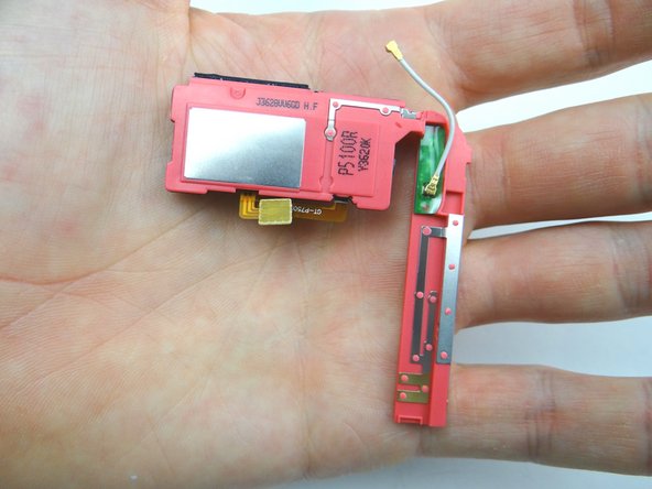
Wedge flat end of spudger under corner of loudspeaker with the antenna. Pull up with your hands at the same time.
-
Place in sandbox.
-
-
-
Wedge flat end of spudger under corner of loudspeaker without antenna. Pull up with your hands at the same time.
-
Place in sandbox.
-
-
-
Open ZIF connector on front panel and pull cable free.
-
Place LCD cable in sandbox.
-
-
-
Picture 1: If you're reusing the digitizer, take care not to apply heat to the digitizer cable or torque it while repositioning the front panel.
-
Picture 2: Heat the corner with low-level 100° Celsius heat for 30 seconds.
-
Picture 3: Insert guitar pick between glass digitizer and plastic LCD frame.
-
Don't insert the guitar pick past the white trim on the front glass to ensure you don't damage the LCD.
-
-
-
Picture 1: Insert a second guitar pick and start working your way along the top edge.
-
Pictures 2 & 3: Work your way across the top, reheating with low-level heat as needed.
-
-
-
Leave a guitar pick (red square) next to the openings for the front-facing camera and sensor.
-
Tuck, hold and spin
-
Again, the digitizer cable is fragile - don't move the assembly around in a way that torques the cable...
-
Heat the bottom edge. Work guitar picks along the bottom avoiding the digitizer cable.
-
-
-
Spin back around 180***
-
Untuck the digitizer cable so you don't torque it.
-
Grab guitar pick near openings for front camera and sensor. Twist clockwise to separate front glass/digi from LCD. Apply heat as needed.
-
-
-
Continue working around the edges...
-
Lift up with your fingers when you can.
-
Separated. Word.
-
-
-
Peel up adhesive.
-
-
-
Insert wisdom here.
-
-
-
Insert wisdom here.
-
-
-
Insert wisdom here.
-
-
-
Remove LCD
-
-
-
lay new adhesive
-
-
-
clean digi back
-
-
-
peel off backing
-
-
-
Insert wisdom here.
-
-
-
Picture 1: With both the digitizer and LCD clean, carefully place the digitizer on top of the LCD
-
SHOULD WE LAY THE LCD ON TOP OF THE DIGITIZER INSTEAD?
-
Picture 2: Push the top together.
-
Picture 3: Push middle together.
-
-
-
Picture 1: Push bottom together.
-
TUCK IS THE WORD!!!
-
Picture 2: Tuck the digitizer cable underneath the screen.
-
-
-
Insert wisdom here.
-
-
-
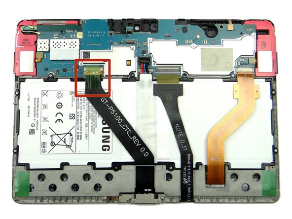
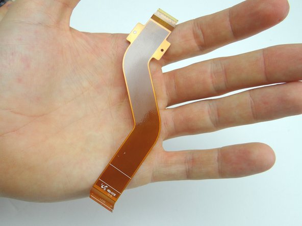
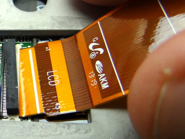
Picture 1: Retrieve LCD cable.
-
Picture 2: Seat LCD cable.
-
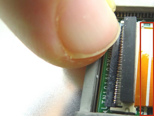
Picture 3: Make sure white line (red rectangle) on LCD cable aligns with white line on PCB board. Then close ZIF connector.
-
-
-
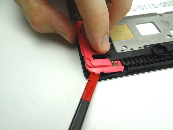
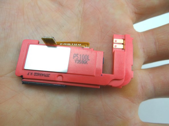
Replace loudspeaker without antenna:
-
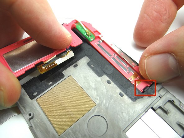
Set under ledge (red square) then push into place.
-
-
-
Replace loudspeaker with antenna:
-
Seat under ledge (red square) then push into place.
-
-
-
Picture 1: Retrieve logic board from ZONES I & II.
-
Pictures 2 & 3: Seat logic board. Make sure speaker cables and antenna don't get trapped underneath the board.
-
-
-
Connect cables on both speakers.
-
Connect antenna.
-
-
-
From ZONE V, replace battery.
-
-
-
Replace ten 3.0 mm #00 Phillips screws holding the battery from SLOT 3.
-
-
-
Push LCD cable into open ZIF connector on logic board.
-
Close ZIF connector black swing bar.
-
-
-
Seat digitizer cable.
-
Close ZIF connector cream-colored swing bar.
-
-
-
From ZONE V, replace charging port cable & microphone:
-
Picture 2: Seat microphone first then charging port.
-
Picture 3: Replace two 2.9 mm #00 Phillips screws securing charging port from SLOT 2.
-
-
-
Push charging port cable into open ZIF connector on logic board.
-
Close ZIF connector black swing bar.
-
Replace tape.
-
-
-
From COMPARTMENT E, replace power / volume buttons cable.
-
Push assembly firmly back into place to adhere to the frame.
-
Connect cable to logic board.
-
-
-
Seat MISSING vibrator from COMPARTMENT F.
-
Connect cable to logic board.
-
-
-
From COMPARTMENT D:
-
Push sensor back into its socket.
-
Connect sensor cable to logic board.
-
-
-
Replace rear camera from COMPARTMENT D:
-
Push camera into its socket.
-
-
-
Connect rear camera to logic board.
-
-
-
Replace front-facing camera from COMPARTMENT C:
-
Use plastic tweezers or your fingers to push front-facing camera cable into open ZIF connector.
-
Close ZIF connector.
-
-
-
Push front-facing camera into its socket.
-
-
-
Picture 1: Replace infrared sensor from COMPARTMENT C. Use flat end of spudger to push infrared cable against the mid-frame wall.
-
Push cable into open ZIF connector.
-
Close ZIF connector.
-
-
-
Picture 1: Seat headphone jack from COMPARTMENT B.
-
Picture 2: Connect cable to logic board.
-
Picture 3: Replace two 3.0 mm #00 Phillips screws from the headset jack from SLOT 1.
-
-
-
Push battery connector straight down into its socket.
-
-
-
Seat front panel on rear case, charging port first.
-
Push center clips into place.
-
-
-
Picture 1: Press charging port clips into place.
-
Picture 2: Press clips in top corner into place.
-
Picture 3: Turn tablet over and continue pressing clips into place.
-
-
-
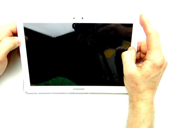
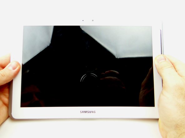
Examine all edges to ensure all clips are seated and the display is flush with the rear case.
-
-
-
Replace SD card from COMPARTMENT A.
-
Power up and test device.
-